What Is an RF Divider and How Does It Work?
An Rf Divider is a passive microwave component that takes one input signal and distributes power across two or more output ports. You will find one in a receiver rack, a test bench, or a compact antenna system. Its job sounds simple. The details are not.
In a common two-way design, each output receives roughly half the input power, less the divider’s insertion loss. A Wilkinson divider, for example, uses transmission lines and an isolation resistor to help reduce interaction between output ports. Frequency matters. So do impedance match, port isolation, power handling, and physical layout. A tidy schematic can still behave differently on a real board.
The wider market shows why these components matter, though it does not measure dividers alone. Grand View Research estimated the global RF components market at USD 26.7 billion in 2023 and projected growth through 2030. That figure is context, not proof of demand for any single divider type. David M. Pozar, whose Microwave Engineering is a standard reference for microwave network analysis, offers a useful design lens. A practical paraphrase of that lens is: “A power split only works well when matching, isolation, and bandwidth suit the system.” The ideal model can mislead. Real cables, connectors, and tolerances leave fingerprints on measured results. This guide explains how an Rf Divider works, how common designs differ, and which specifications deserve a close look before selection.
Definition and Core Function of an RF Power Divider
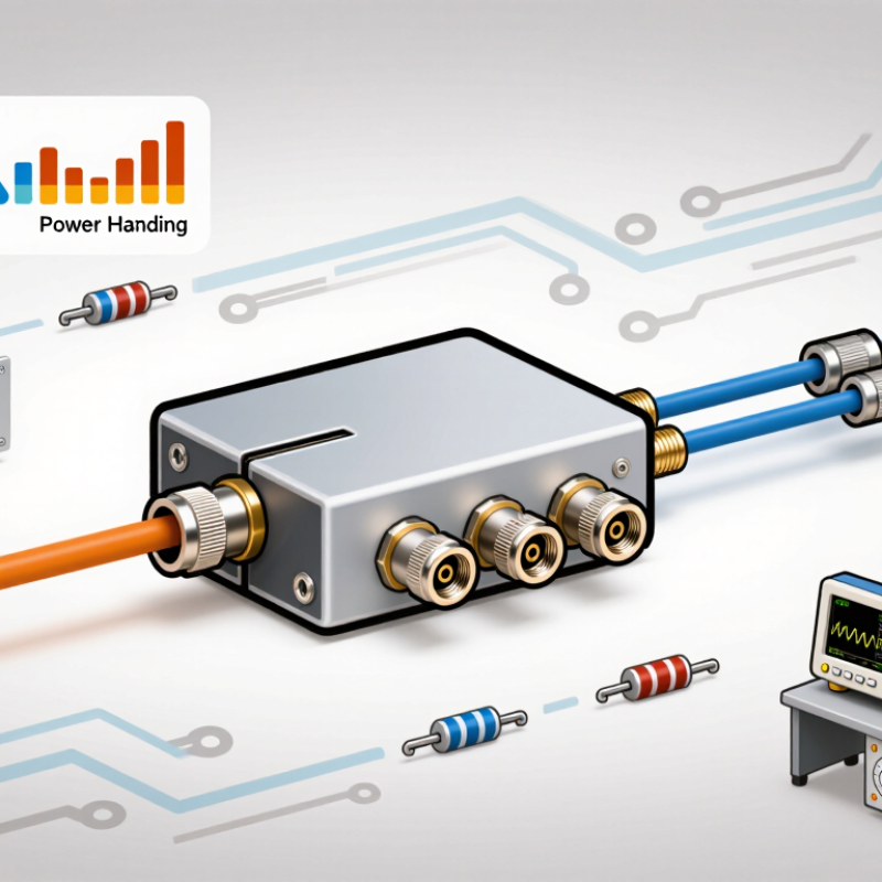
An RF Power Divider is a passive network that takes one radio-frequency signal and sends portions of it to two or more output ports. Its core function is controlled signal distribution, not signal amplification. In an ideal equal two-way divider, each output receives half the input power, a reduction of about 3 dB. Real devices add some extra loss through conductors and components. Small details matter: the operating frequency, impedance, and number of outputs all affect performance.
Inside, transmission lines and resistive elements guide the signal and help manage energy that might otherwise reflect between ports. Designs such as Wilkinson dividers can provide good output isolation across a specified frequency range. Isolation helps prevent a changing load on one output from strongly disturbing another. That sounds straightforward, but a divider is not automatically suitable for every setup. For example, connecting it to mismatched cables can increase reflections and alter measured output levels. On a test bench, an engineer may check each port with a calibrated power meter or network analyzer, then compare the readings with the device specification. A little imbalance can remain. Its acceptable size depends on the application.
Ideal equal two-way RF power divider: The input signal is split equally between two output ports. Each output is 3.01 dB below the input, assuming an ideal divider with no excess loss.
Equal Splits: 3.01 dB per Output for Two-Way Division
An RF divider takes one radio-frequency input and delivers portions of its power to multiple outputs. In an ideal two-way divider, each output receives half the input power. Half the power corresponds to a level of about 3.01 dB below the input.
That figure describes the split, not the divider’s entire real-world loss. A practical unit also has insertion loss from conductors, components, and imperfect matching. So, if a signal enters at 0 dBm, each output may measure slightly below -3.01 dBm. The exact reading depends on frequency, construction, and the loads connected to the ports. Small details matter.
For a useful check, connect both outputs to matched 50-ohm loads and measure them with suitable RF equipment. Unequal readings can point to cable differences, poor connections, or limited amplitude balance. Also check isolation: energy reaching one output should not strongly disturb the other. It is easy to focus only on the 3.01 dB figure; I would still verify the datasheet’s frequency range and measured insertion loss before choosing a divider.
Wilkinson Design: 70.7 Ω Quarter-Wave Arms in a 50 Ω System
An RF divider takes one input signal and delivers power to two or more output ports. A Wilkinson divider is a common choice when equal outputs and good port isolation matter. In a 50-ohm system, its two branches are designed as 70.7-ohm transmission lines. That value is approximately 50 × √2; it is not a resistor value.
Each branch is a quarter wavelength long at the chosen center frequency. At that frequency, the transformed impedances combine to present about 50 ohms at the input. The outputs are ideally equal in amplitude and in phase. A 100-ohm resistor connects the two output ports. With balanced signals, little current flows through it. If one output sees a mismatch, the resistor helps absorb the imbalance and limit coupling between ports.
That is the ideal. In a real layout, the quarter-wave length depends on the substrate’s effective dielectric constant, not just free-space wavelength. Even small changes in trace width, board thickness, or connector launch can shift performance. A divider tuned for 2 GHz may show more loss or poorer isolation away from that frequency. Simulation helps, but a measured prototype still matters. I would check insertion loss, return loss, and output balance across the intended band, because a neat schematic can hide a slightly imperfect board.
Port Isolation: The 100 Ω Resistor in a 50 Ω Wilkinson Divider
An RF divider splits one input signal between output ports. In a two-way, 50 Ω Wilkinson divider, each quarter-wave branch is about 70.7 Ω, and a 100 Ω resistor connects the outputs. These values follow the classic design equations presented by E. J. Wilkinson in his 1960 IEEE paper, “An N-Way Hybrid Power Divider.” The resistor is not a simple load across the signal path.
With matched loads and equal, in-phase outputs, both resistor terminals sit at nearly the same voltage. Little current flows through it. That is the point. If the outputs become unequal, their voltage difference drives current through the resistor. The resistor dissipates some differential-mode energy, reducing coupling between output ports while preserving the desired equal split. In a practical bench test, this behavior appears as improved port-to-port isolation, not extra output power.
The distinction matters. The resistor cannot correct every mismatch, and its isolation depends on frequency, layout, and component parasitics. Quarter-wave branches work best near their design frequency, so performance changes across a wider band. A small resistor mounted with long leads can also weaken isolation. The textbook 100 Ω value is a starting point, not a promise of perfect measurements.
Bandwidth, Insertion Loss, and Power Ratings Across Operating Frequencies
An RF divider splits one input signal into two or more output paths. Its bandwidth is the frequency range where key specifications remain within limits—not simply the range where a signal appears at the output. Check insertion loss, amplitude balance, and return loss across the full band. IEEE Std 145-2013 provides standard terminology for antennas and related RF measurements; divider performance should still be verified against measured S-parameters for the specific device.
For an ideal equal two-way split, each output is 3.01 dB below the input. Real dividers add excess insertion loss through conductor, dielectric, and resistor losses. That loss can rise near a band edge, where a measurement may also show poorer balance. Power ratings need similar care: a divider may specify maximum input power, output power, or both, under stated temperature and load conditions. Mismatch can concentrate heat in a small component, so the rating is not a promise under every setup. Small numbers matter.
Tips: Compare data at your actual operating frequency, not just the headline bandwidth. Confirm whether the power figure is continuous-wave or peak, and check the required load conditions. For a quick bench check, use matched terminations and calibrated cables; cable loss can make a divider look better or worse than it is. Measurements are imperfect, too, especially near the limits of the test setup.