7 Tips for Choosing the Right Check Valves?
Choosing the right check valves is a small decision with major consequences for pumps, pipelines, and process safety. A failed valve can allow reverse flow, water hammer, contamination, or costly equipment damage. The choice is rarely just about pipe size.
Market evidence shows why careful selection matters. Grand View Research estimated the global industrial valves market at approximately USD 77.7 billion in 2023, with continued growth expected through 2030. MarketsandMarkets has also identified check valves as a steady-growth segment, supported by expanding water treatment, oil and gas, chemical, and power infrastructure. These figures suggest strong demand, but they do not guarantee that every valve suits every application.
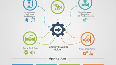
Real-world experience often reveals the difference. A swing check valve may work well on a horizontal wastewater line, while a wafer check valve can save space between flanges. A spring-loaded design may close faster and reduce reverse flow, but it can also create higher pressure loss. Small details matter: fluid viscosity, installation direction, temperature, pressure, flow speed, and maintenance access should all be reviewed.
Technical standards provide a reliable foundation. API 6D addresses pipeline valves, while ISO 5208 defines pressure-testing requirements for metallic valves. Still, standards cannot replace engineering judgment. Selection mistakes happen, especially when buyers focus only on price or nominal diameter. The following seven tips examine the practical factors behind dependable check valves, while acknowledging an uncomfortable truth: no single design is perfect for every system.
Understand How Check Valves Control One-Way Flow
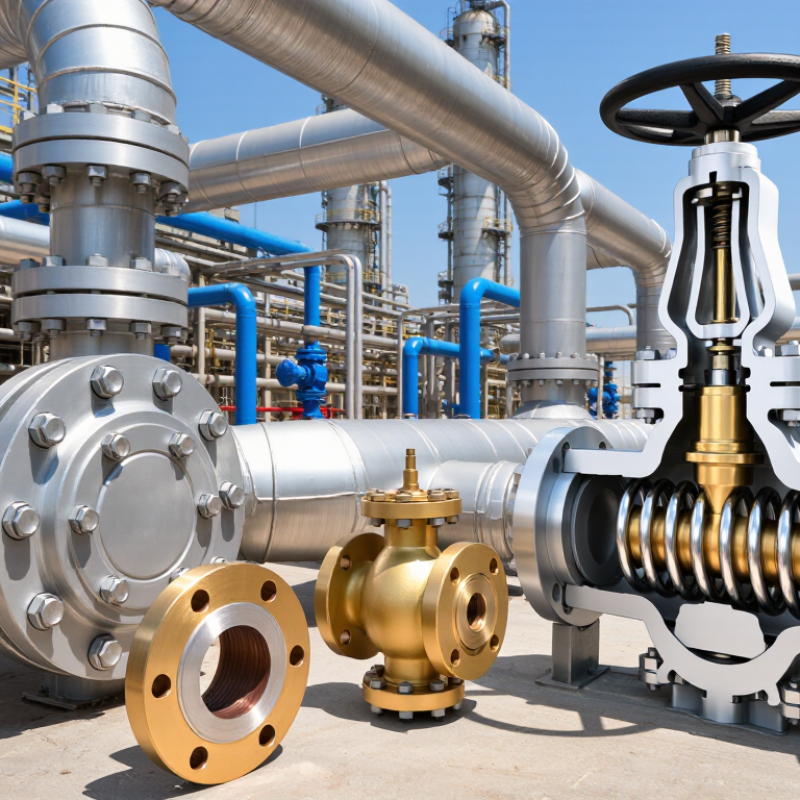
Check valves control one-way flow by opening under forward pressure and closing when flow reverses. This simple action protects pumps, prevents pipe hammer, and limits backflow contamination.
The U.S. Department of Energy reports that pumping systems can represent about 25% of industrial electricity use. Poor valve selection can increase pressure loss and operating costs.
Tip 1
Match the valve type to the fluid. Swing valves suit cleaner liquids, while spring-loaded designs respond faster.
Tip 2
Check the cracking pressure. A high setting may restrict low-flow equipment.
Tip 3
Compare the valve’s flow coefficient with the pipe diameter. Smaller passages create measurable losses.
Tip 4
Confirm pressure and temperature ratings from the technical datasheet, not appearance.
Tip 5
Study reverse-flow risk and water-hammer exposure. Fast closure is helpful, but sudden closure can also create damaging pressure waves.
Tip 6
Install the valve in the correct direction, with enough straight pipe for stable flow.
Tip 7
Plan inspection access. Debris, worn seats, and weak springs can prevent complete closure.
ANSI/HI guidance and API 598 testing practices emphasize verified performance, leakage control, and documented testing.
Still, a perfect paper selection may fail in a dirty pipeline. Real operating data matters more than assumptions.
Define Pressure, Temperature, and Flow Requirements
Choosing a check valve starts with defining pressure, temperature, and flow requirements. These figures must reflect normal operation and sudden changes. A pump may create a brief pressure surge during startup or shutdown. That surge can exceed the stated line pressure.
Record the maximum working pressure, design pressure, vacuum conditions, and expected pressure drop. The U.S. Department of Energy’s Improving Pumping System Performance sourcebook reports that pumping systems can consume 25% to 50% of industrial facility electricity. Excessive valve resistance can increase this hidden cost. Small details matter.
Temperature data should include the fluid, ambient conditions, and cleaning cycles. Material ratings can change sharply with heat. ASME B16.34 connects valve pressure ratings with temperature and material considerations, but published tables cannot replace project-specific verification. Flow data needs more than an average value. Identify minimum, normal, maximum, and reverse-flow conditions. The Hydraulic Institute emphasizes evaluating pump systems across changing operating points, not only at peak duty. A valve that works at peak flow may chatter during low flow.
Ask for transient calculations when pipelines are long or flow stops quickly. Water hammer is easy to underestimate. I have seen specifications copied from older projects without checking actual density or viscosity. That is a costly habit. Reconfirm every number with process engineers, pump curves, and site measurements before selecting the valve type, size, and closing speed.
Verify Installation, Maintenance, and Quality Standards
7 Tips for Choosing the Right Check Valves
Verify Installation, Maintenance, and Quality Standards
Tip 1: Confirm the flow direction before installation. Check the arrow on the valve body and compare it with the piping plan. The valve should sit squarely between aligned pipes. Forced alignment can increase disc wear and cause leakage. Support nearby pipework, especially when the valve is heavy. Small installation errors often become expensive repairs.
Tip 2: Inspect the valve after commissioning. Listen for hammering, watch pressure changes, and check every connection for seepage. Record the test pressure, date, and observed results. During maintenance, remove deposits and examine the seat, spring, hinge, or disc. Follow the manufacturer’s service limits, but do not rely on paperwork alone. Field conditions can differ from the original design.
Tip 3: Review quality standards before purchasing. Match the pressure, temperature, fluid compatibility, and connection rating to the system. Request material certificates, inspection records, and leakage-test results from qualified suppliers. Check whether the valve complies with applicable ASME, API, ISO, or local requirements. Standards matter, but they are not a substitute for engineering judgment.
A practical checklist should include spare-part availability and clear maintenance intervals. It should also identify who approves installation and testing. I would reconsider any selection based only on low price. That shortcut may seem reasonable, yet repeated shutdowns can cost much more. Even experienced teams miss details, so independent verification remains valuable.
7 Tips for Choosing the Right Check Valves: Verify Installation, Maintenance, and Quality Standards
Use the pressure-class reference below to compare common ASME B16.5 flange classes at 38°C (100°F). The values are rounded from the standard pressure-temperature ratings and should be checked against the valve manufacturer's certified pressure and temperature limits.
Key Selection Checks
- Verify the flow direction and install the valve according to the marked arrow.
- Size the valve for the required flow rate, velocity, and acceptable pressure drop.
- Confirm that the pressure class and temperature rating exceed the system design conditions.
- Match the end connection, face-to-face dimensions, and piping standard.
- Request leakage-test documentation based on an applicable standard such as ISO 5208 or API 598.
- Provide access for inspection, cleaning, replacement, and routine maintenance.
- Check material certificates, traceability, casting quality, and applicable quality-control records.
Reference: ASME B16.5 pressure-temperature ratings for carbon-steel flange classes at 38°C (100°F). Pressure class selection must also consider the actual valve body, trim materials, fluid, temperature, and applicable project standards.