
Blog

7 Best RF Coaxial Connectors for Global Buyers

Choosing an RF connector is not a minor purchasing decision. It can influence signal loss, return loss, durability, and installation time. For global buyers, the right Rf Coaxial Connector must also match regional supply, documentation, and quality expectations.

Dr. David M. Pozar, a respected microwave engineering author, offers a useful design principle: “The connector is part of the circuit, not an afterthought.” This idea matters in real installations. A connector may look robust on a test bench, yet fail after repeated mating, vibration, moisture, or temperature changes. Experienced buyers should examine impedance, operating frequency, VSWR, insertion loss, plating, coupling style, and cable compatibility. Datasheets should be checked carefully. Marketing language is not enough.

This guide reviews seven strong Rf Coaxial Connector options for international procurement teams, engineers, integrators, and maintenance specialists. The comparison considers common families such as SMA, SMB, N-Type, BNC, TNC, MCX, and 2.92 mm connectors. Each type serves a different balance of frequency, size, mechanical strength, and cost. Some perform well in outdoor systems. Others suit compact equipment or laboratory testing.

No ranking is perfect. Application details can change the outcome. A low-cost connector may become expensive after field replacements. A premium model may offer unnecessary performance for a simple control system. Buyers should confirm manufacturer certifications, traceability, test conditions, and regional availability before ordering. Small details matter. Even cable preparation can affect final performance. Our recommendations aim to support informed decisions, while recognizing that connector selection still requires project-specific engineering review.
7 Best RF Coaxial Connectors for Global Buyers

RF Coaxial Connectors: Structure, Function, and Common Applications

7 Best RF Coaxial Connectors for Global Buyers

RF Coaxial Connectors: Structure, Function, and Common Applications

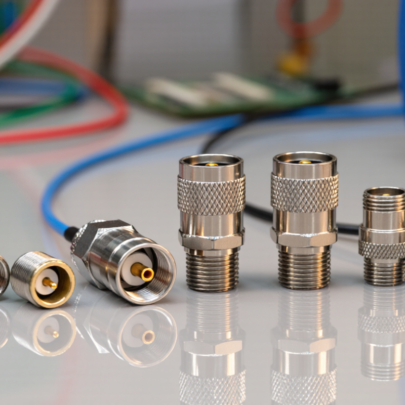
An RF coaxial connector joins a cable to equipment while preserving controlled signal flow. Its structure includes a center conductor, dielectric insulator, outer conductor, and protective body. The center pin carries radio-frequency energy. The outer conductor contains interference and supports shielding. The dielectric maintains spacing between both conductors. Small gaps matter.

Common connector families include BNC, TNC, SMA, SMB, N-type, F-type, and UHF-type designs. Their differences involve impedance, frequency range, locking method, size, and cable compatibility. A threaded interface usually resists vibration better than a push-fit interface. However, a quick connection can save time in test environments. Buyers should verify 50-ohm or 75-ohm requirements before ordering. Mixing them may increase signal reflection.

Applications vary widely. BNC connectors often support laboratory instruments, cameras, and temporary test cables. N-type connectors suit outdoor radio systems because their sealed bodies handle moisture more effectively. SMA and SMB designs fit compact wireless modules and circuit assemblies. F-type connectors commonly serve television and broadband installations. In field inspections, damaged threads, loose center pins, and poor crimping remain frequent failure points. A connector may look correct but still produce high VSWR. I have found that cable diameter is often overlooked during selection. Installation tools, plating quality, weather sealing, and mating-cycle ratings deserve equal attention. Specifications help, but practical fit sometimes needs a second check.

Typical Maximum Frequency of RF Coaxial Connectors

This comparison shows commonly published upper frequency ratings for widely used RF coaxial connector types. Actual performance depends on connector design, cable assembly quality, and the specific interface configuration.

Key Criteria for Comparing RF Coaxial Connectors Worldwide

7 Best RF Coaxial Connectors for Global Buyers

Key Criteria for Comparing RF Coaxial Connectors Worldwide

Choosing an RF coaxial connector starts with the application, not appearance. Check impedance, operating frequency, and allowable voltage first. A 50-ohm connector may suit wireless equipment, test systems, and antennas. However, small differences in design can change return loss at higher frequencies. Review insertion loss, VSWR, shielding performance, and connector dimensions together. I have learned that a connector fitting perfectly can still perform poorly in a high-frequency assembly.

Mechanical reliability also matters across international supply chains. Compare mating cycles, locking strength, contact materials, and plating thickness. Outdoor equipment needs sealing against moisture, dust, vibration, and temperature changes. Indoor laboratory equipment may need better repeatability instead. Confirm cable compatibility before ordering. Metric and imperial dimensions can create costly mistakes. Ask suppliers for test reports, dimensional drawings, material declarations, and batch traceability. Documentation is not exciting, but it exposes weak quality control.

Tips: Test samples before approving large quantities. Measure return loss with calibrated equipment. Inspect the center contact under magnification. Keep spare connectors from the same production batch. Standards help, but field conditions still deserve attention. I would also compare lead times and after-sales support, because a technically excellent connector is not useful when replacement parts remain unavailable. My own comparisons are sometimes incomplete; real installation feedback can reveal weaknesses that laboratory data misses.

7 Best RF Coaxial Connectors for Global Buyers - Key Criteria for Comparing RF Coaxial Connectors Worldwide

Connector Type Common Impedance Typical Operating Frequency Coupling and Locking Method Typical Electrical Performance Environmental and Mechanical Suitability Common Global Applications Main Advantages Important Limitations Key Buying Criteria
7/16 DIN 50 Ω DC to approximately 7.5 GHz for common versions Screw coupling; high contact pressure Very low passive intermodulation when correctly installed; high power-handling capability; low insertion loss Designed for outdoor infrastructure; commonly available with weatherproof sealing and rugged bulkhead configurations Mobile-network base stations, broadcast systems, distributed antenna systems, and high-power RF equipment Excellent mechanical strength, power capacity, and resistance to passive intermodulation Larger, heavier, and generally more expensive than compact connector families; not ideal for miniature equipment Verify PIM rating, power rating, weatherproofing, cable size, plating, and required international interface standard
N-Type 50 Ω 75 Ω Common versions operate from DC to 11 GHz; precision designs may extend higher Threaded coupling Good shielding, low leakage, stable impedance, and comparatively low insertion loss Suitable for indoor and outdoor use when supplied with appropriate seals; robust against vibration Antennas, wireless infrastructure, test equipment, microwave links, and industrial RF systems Strong general-purpose performance and broad worldwide availability Bulkier than SMA, TNC, and miniature connectors; 50 Ω and 75 Ω versions must not be mixed indiscriminately Confirm impedance, operating frequency, cable interface, sealing grade, mating dimensions, and maximum power
SMA 50 Ω DC to 18 GHz for many standard versions; specialized versions may reach higher frequencies Threaded coupling Good high-frequency performance, effective shielding, and relatively low reflection when properly matched Best suited to indoor, laboratory, and protected equipment environments; ruggedized versions are available RF modules, antennas, measurement equipment, wireless devices, and microwave assemblies Compact, widely standardized, and suitable for high-frequency applications Small threads can be damaged by over-tightening; standard versions are not automatically weatherproof Check frequency rating, gender, cable diameter, torque requirement, plating, and environmental sealing
TNC 50 Ω 75 Ω Common versions operate from DC to approximately 11 GHz Threaded coupling Better vibration resistance than push-on coupling; consistent shielding and impedance control Suitable for mobile, outdoor, and industrial environments when a sealed version is selected Outdoor antennas, navigation systems, cellular equipment, industrial controls, and test systems More secure under vibration than bayonet-style connectors while retaining a moderate form factor Usually more expensive and slower to mate than BNC; impedance variants require careful compatibility checks Evaluate vibration level, sealing, impedance, frequency range, cable retention, and mating-cycle requirements
BNC 50 Ω 75 Ω Common versions operate from DC to approximately 4 GHz; some precision types support higher frequencies Bayonet coupling; quick quarter-turn mating Reliable general-purpose RF performance with fast connection and disconnection Well suited to laboratory and equipment-panel use; outdoor service requires suitable environmental protection Test instruments, video systems, radio equipment, data acquisition, and laboratory connections Fast to mate, easy to operate, and widely recognized across international markets Lower frequency capability than SMA or many N-Type designs; bayonet locking is less resistant to severe vibration than threaded coupling Confirm 50 Ω or 75 Ω impedance, frequency requirement, cable type, panel cutout, and required mating cycles
SMB 50 Ω 75 Ω Common versions operate from DC to approximately 4 GHz Snap-on coupling Compact connection with moderate RF performance and convenient installation Primarily intended for protected indoor equipment and internal assemblies; not normally chosen for exposed outdoor service Automotive electronics, instrumentation, communication modules, and internal RF connections Small size, quick installation, and good suitability for space-constrained equipment Lower mechanical retention and environmental protection than threaded alternatives; limited suitability for repeated harsh-field mating Check retention force, impedance, operating frequency, connector orientation, cable construction, and enclosure protection
MCX 50 Ω 75 Ω Common versions operate from DC to approximately 6 GHz Snap-on coupling Good RF performance for its small size; suitable for compact cable-to-board and board-to-board assemblies Normally used inside protected products; specialized versions may support automotive or light industrial environments GNSS equipment, compact wireless devices, embedded systems, measurement modules, and automotive electronics Very compact, lightweight, and convenient for high-density electronic designs Lower mechanical robustness than threaded connectors; unsuitable for direct exposure unless specifically sealed and qualified Verify PCB footprint, mating height, retention, impedance, cable bend radius, vibration rating, and lifecycle requirements
Selection note: Frequency range, power rating, voltage rating, return loss, insertion loss, environmental protection, and mating-cycle performance vary by manufacturer, connector gender, cable assembly, and specific design. Always compare the applicable IEC or equivalent specification and the complete cable-connector assembly rather than relying only on the connector family name.

Seven Leading RF Coaxial Connector Types for Global Buyers

Seven Leading RF Coaxial Connector Types for Global Buyers

Global buyers commonly compare seven RF coaxial connector types: SMA, SMB, SMC, BNC, TNC, N, and MCX. SMA supports compact, high-frequency assemblies, while SMB offers quick snap coupling. SMC provides threaded security in tighter spaces. BNC remains practical for test equipment. TNC improves vibration resistance. N connectors suit outdoor and higher-power systems. MCX reduces size in automotive and embedded electronics.

MarketsandMarkets reports that the global RF connectors market is projected to grow from about USD 3.8 billion in 2023 to USD 5.5 billion by 2028.

Frequency alone should not decide the purchase. Buyers need to check impedance, insertion loss, voltage standing wave ratio, mating cycles, and environmental sealing. A 50-ohm system should not receive a casual 75-ohm substitute. IEC 61169 standards help define interface and performance requirements. Grand View Research identifies telecommunications, automotive, and aerospace electronics as important demand areas. This supports careful selection across regional supply chains.

Small details matter. A field technician may notice loose coupling before a laboratory report does. Stainless steel improves corrosion resistance, but it can increase cost and weight. Gold-plated contacts often improve durability, yet plating thickness still requires verification. I would not trust a connector based only on a polished datasheet. Cable diameter, torque control, and actual test frequency can change results. The overlooked point is installation quality. Even the best connector can fail after poor preparation.

Connector Standards, Compatibility, and Regional Market Requirements

Choosing the right RF coaxial connector starts with standards, not appearance. The seven practical options are Type N, SMA, SMB, SMC, TNC, BNC, and 7/16 DIN. Each serves different frequency, power, size, and installation needs. Type N suits outdoor systems because its threaded design resists vibration and moisture. SMA offers compact performance for test equipment and wireless modules. BNC supports quick connections, while TNC improves stability in mobile equipment. SMB and SMC save space, but they require careful handling. For high-power infrastructure, 7/16 DIN often provides stronger mechanical performance.

Compatibility depends on more than connector gender. Check impedance, usually 50 or 75 ohms, along with operating frequency, cable diameter, and contact plating. Confirm the applicable IEC or regional specification before ordering. North American projects may request different documentation from European or Asian tenders. Some markets also demand RoHS declarations, weatherproof ratings, or specific test reports. A connector can fit physically and still fail electrically. That mistake remains surprisingly common. In field inspections, poor cable preparation often causes more loss than the connector itself.

Tips:Request dimensional drawings and return-loss data. Test sample assemblies before volume purchasing. Verify local approvals and packaging requirements. Keep spare mating parts onsite. One lesson worth remembering: universal compatibility is mostly a convenient myth. Regional installers may also prefer familiar interfaces, even when newer designs look better.

How to Choose the Right RF Coaxial Connector for Your Project

7 Best RF Coaxial Connectors for Global Buyers

How to Choose the Right RF Coaxial Connector for Your Project

Choosing the right RF coaxial connector starts with the equipment, not appearance. The seven common options include SMA, N-type, BNC, TNC, F-type, U.FL, and MCX. SMA supports compact, high-frequency assemblies. N-type offers stronger outdoor performance. BNC provides quick bayonet coupling. TNC improves vibration resistance with threaded coupling. F-type works well for broadband signal systems. U.FL saves space inside compact devices. MCX suits small equipment with frequent layout limits.

Check impedance before ordering. Most RF systems use 50 or 75 ohms. A mismatch can increase reflection, insertion loss, and signal distortion. Confirm the connector’s rated frequency, voltage, and power handling. Datasheets matter more than product photos. Use a vector network analyzer when performance is critical. Measure return loss after assembly, not only before installation.

Environmental details often decide the result. Outdoor projects may require sealing, corrosion-resistant plating, and an appropriate ingress rating. Match the connector to the cable diameter and dielectric size. A perfect connector can fail after poor crimping. Torque values also deserve attention. Too much force may damage threads or the interface. Too little can create unstable contact. No connector wins every project. A compact choice may be excellent electrically but difficult to repair. Review mating cycles, available tools, lead time, and replacement access. One decision can still be wrong.