Selecting the right butterfly valve is not a simple matter of matching pipe diameter. The valve must suit the medium, pressure, temperature, flow pattern, and operating frequency. A cooling-water line may need a resilient-seated design, while abrasive slurry can demand stronger materials and a carefully protected disc. Small details matter. A damaged seat can cause leakage, vibration, or costly downtime.
Valve engineer James R. Patterson offers a useful design reminder: “Choose the valve for the system, not merely for the pipe.” That principle keeps the selection process practical. Engineers should examine whether the valve will operate manually, pneumatically, or electrically. They should also check face-to-face dimensions, flange standards, shutoff requirements, and available maintenance space. A compact butterfly valve may fit a crowded plant area, but its actuator still needs enough clearance for safe servicing.
This guide will examine the main butterfly valve types and their suitable applications. It will compare wafer, lug, and flanged configurations. It will also consider seat materials, disc alloys, torque requirements, and control accuracy. Field experience often reveals overlooked problems. A valve that performs well during testing may struggle with temperature changes or contaminated fluid. Selection is never perfect. Assumptions must be questioned. Reliable results come from combining manufacturer data, system calculations, and realistic operating conditions.
Choosing a butterfly valve starts with defining real system conditions, not selecting by pipe size alone. Record the medium, temperature, pressure, flow range, solids content, and operating frequency. A DN300 valve handling chilled water needs different materials from one carrying abrasive slurry. Check shutoff pressure carefully. Maximum pressure and normal pressure are not the same.
The IEA reports that industry consumes about 37% of global final energy. Efficient flow control therefore matters, especially in large pumping and cooling systems. Estimate pressure drop across the valve at minimum, normal, and maximum flow. Consider cavitation, corrosion, shaft torque, and actuator response. API 609 provides design guidance for butterfly valves, while ISO 5752 defines face-to-face dimensions. These references improve consistency, but field conditions can still expose weak assumptions. I once saw a valve sized correctly on paper, yet its actuator struggled because frequent cycling was ignored.
Tips: Build a simple duty table before requesting quotations. Include startup pressure, emergency temperature, fluid viscosity, and cleaning chemicals. For water systems, review the UN World Water Development Report 2024, which identifies agriculture as responsible for roughly 70% of global freshwater withdrawals. That scale makes material compatibility and leakage control practical priorities. Specify the required seat, disc, body, and shaft materials. Confirm the valve’s tested shutoff class. Leave room for doubt. A neat datasheet can hide an imperfect operating profile.
Define the system pressure, operating temperature, media compatibility, shut-off requirement, and cycling frequency before selecting a valve design.
The chart shows representative upper service limits commonly associated with each butterfly valve design. Resilient-seated valves are generally suitable for lower-temperature utility and water services, while double-offset and triple-offset designs are better suited to higher pressure, temperature, and tighter shut-off requirements. Always verify the final selection against the valve manufacturer's technical datasheet and applicable standards.
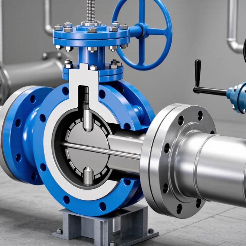
Choosing the right butterfly valve starts with understanding its type and operating mechanism. Concentric valves use a centered disc and flexible seat, making them practical for water, air, and general utility lines. They are compact, economical, and easy to maintain. Double-offset valves reduce disc-to-seat contact during operation. This design lowers wear in larger pipelines or moderate-pressure service. Triple-offset valves create a cam-like motion and metal sealing surface. They suit higher temperatures, demanding cycles, and applications requiring tight shutoff. The detail matters.
The operating mechanism also affects reliability. A hand lever works well on small valves needing quick, occasional adjustment. Gear operators provide better control on larger diameters, where direct force becomes uncomfortable. Pneumatic actuators open and close quickly, which helps process systems respond to changing conditions. Electric actuators support remote operation and precise positioning. Hydraulic units deliver strong movement, but they need careful fluid management and inspection.
In field maintenance, valve size is not the only concern. A lightweight valve may fit the pipe, yet fail under frequent cycling or abrasive media. Check pressure, temperature, fluid chemistry, flow direction, and available space around the actuator. Verify the flange standard and shaft orientation before installation. Small details matter. I have seen poorly matched seats cause leakage after only a short service period. Selection tables are useful, but they cannot replace actual operating data. An imperfect choice often looks acceptable until the first difficult shutdown.
| Valve Type or Operating Option | Basic Design | Typical Pressure and Temperature Capability | Primary Advantages | Important Limitations | Best-Fit Applications | Selection Considerations |
|---|---|---|---|---|---|---|
| Wafer Butterfly Valve | Thin, lightweight body installed between two pipe flanges. The valve is normally centered by the flange bolts. | Commonly used for low- to medium-pressure services. Temperature capability depends mainly on the seat material and body construction. | Compact face-to-face length, low weight, simple installation, and generally lower material cost. | It usually cannot provide end-of-line service unless the specific design is approved for that condition. Removing downstream piping may be required for maintenance. | Water distribution, cooling water, HVAC, irrigation, and general utility lines. | Confirm flange compatibility, pipe alignment, disc clearance, and whether the valve is suitable for dead-end service. |
| Lug Butterfly Valve | Threaded inserts or lugs are cast or machined into both sides of the body, allowing independent bolting to each flange. | Commonly selected for low- to medium-pressure systems; the allowable rating is determined by the valve body, seat, and applicable standard. | Can often be removed from one side of the line while the opposite side remains bolted. It may also support approved dead-end applications. | Usually heavier and more expensive than a wafer design. Bolt alignment and thread condition require careful attention. | Process isolation, water treatment, chemical utility lines, and systems requiring sectional maintenance. | Check the manufacturer's dead-end pressure rating and ensure the lug pattern matches the pipeline flanges. |
| Flanged Butterfly Valve | Valve body has integral flanges that bolt directly to mating pipe flanges. | Often used where higher mechanical strength, easier alignment, or more robust pressure containment is required. Rating varies by design standard. | Good flange alignment, strong installation structure, and convenient removal as a complete flanged assembly. | Longer face-to-face dimensions, greater weight, and higher material and installation cost than wafer-style valves. | Larger pipelines, industrial utilities, pump systems, and applications with frequent disassembly requirements. | Verify flange drilling, face-to-face dimension, gasket requirements, bolt loads, and available installation space. |
| Resilient-Seated Concentric Valve | The disc stem is centered in the pipe, and the disc seals against an elastomeric seat around the body circumference. | Generally suited to moderate temperatures and clean or mildly contaminated fluids. The elastomer determines much of the temperature and chemical resistance. | Reliable bubble-tight shutoff, simple construction, low maintenance, and relatively low operating torque. | Seat materials can be affected by high temperature, aggressive chemicals, hydrocarbons, or abrasive particles. | Potable water, wastewater, air, chilled water, fire protection, and general utility service. | Match the seat compound to the fluid, temperature, pressure, concentration, and cleaning chemicals. |
| High-Performance Double-Offset Valve | The stem is offset from the pipe centerline and the seat axis, reducing disc-to-seat contact during opening and closing. | Suitable for higher pressure and temperature ranges than many concentric resilient-seated valves; exact limits depend on seat and body materials. | Lower seat wear, reduced operating torque, improved service life, and better suitability for larger or more demanding pipelines. | More complex and costly than concentric designs. Some soft-seated versions remain temperature-limited. | Process water, cooling systems, HVAC, power utilities, hydrocarbons, and industrial process lines. | Evaluate shutoff class, seat construction, emissions requirements, flow direction, and required torque margin. |
| Triple-Offset Metal-Seated Valve | Uses three geometric offsets and a conical metal seat to minimize rubbing between the disc and seat during operation. | Designed for high-pressure and high-temperature service when constructed and rated for the application. | Low-friction operation, strong resistance to thermal cycling, reduced seat wear, and suitability for severe isolation duty. | Higher purchase cost, more demanding manufacturing requirements, and less forgiving performance if the line contains excessive solids or poor alignment. | Steam, hot gas, high-temperature process lines, power generation, and critical isolation service. | Confirm the metal-seat leakage class, thermal expansion behavior, material compatibility, and emergency shutdown requirements. |
| Manual Lever Operator | A hand lever rotates the valve shaft directly, usually with a locking plate or indexed position indicator. | Best for small to medium valve sizes and applications where rapid local operation is acceptable. | Simple, fast, inexpensive, and independent of electrical or instrument-air supplies. | Manual effort increases with valve size, pressure differential, packing friction, and seat torque. It is not suitable for remote operation. | Local isolation, small utility lines, maintenance points, and infrequently operated valves. | Check required operating torque, available hand clearance, lockout needs, and whether the valve must be throttled. |
| Manual Gear Operator | A handwheel and gearbox multiply operator input and provide controlled movement of the valve disc. | Commonly used on medium to large valves or where line forces make direct lever operation impractical. | Lower hand effort, improved control, and a convenient option for larger valves. | Slower than a lever, adds mechanical complexity, and may require additional protection in corrosive or outdoor environments. | Large water lines, process piping, cooling systems, and valves requiring deliberate local positioning. | Confirm gearbox output torque, travel stops, handwheel accessibility, and whether the gearbox is self-locking. |
| Pneumatic Actuator | Compressed air drives a quarter-turn rotary actuator. Double-acting units use air for both directions; spring-return units use a spring for the fail position. | Well suited to frequent cycling and hazardous areas when the actuator and accessories are properly certified and configured. | Fast operation, high power-to-weight ratio, and practical fail-open or fail-closed action with spring-return designs. | Requires a reliable air supply, filtration, regulation, and suitable control valves. Air leakage can reduce system efficiency. | Automated process lines, emergency isolation, batching, chemical handling, and high-cycle service. | Size for breakaway, running, and seating torque; include a safety factor and verify air pressure at the actuator. |
| Electric Actuator | An electric motor and gear train rotate the valve shaft, typically with limit switches, torque protection, and position feedback. | Suitable where electrical power and controlled modulation or remote operation are required. Environmental and hazardous-area ratings must be verified. | Precise positioning, easy integration with control systems, and no instrument-air network required. | Generally slower than pneumatic actuation and dependent on electrical power. Incorrect torque settings can damage the valve or actuator. | Water treatment, HVAC, utilities, remote stations, and applications requiring modulating control. | Specify duty cycle, speed, enclosure rating, fail-position requirements, control signal, and available power supply. |
| Hydraulic Actuator | Pressurized hydraulic fluid produces rotary motion through a hydraulic actuator and control circuit. | Used when very high torque, compact power density, or specialized fail-safe performance is required. | High torque output, smooth movement, and good suitability for large valves or demanding operating conditions. | Requires a hydraulic power unit, piping, filtration, and leak control. System complexity and maintenance needs are higher. | Large pipelines, offshore facilities, high-pressure systems, and applications with limited electrical or pneumatic capacity. | Assess hydraulic pressure, fluid compatibility, leakage risk, emergency operation, and the required response time. |
| Throttling or Control Service | The disc is positioned at intermediate angles to regulate flow rather than only provide open or closed isolation. | Applicable only when the valve and seat are designed for the expected pressure drop, velocity, and cycling frequency. | Compact design, relatively low weight, and economical flow control in many large-diameter lines. | High pressure drop or operation near the closed position can cause noise, vibration, cavitation, erosion, and accelerated seat wear. | Cooling-water control, ventilation, combustion-air systems, and selected process-flow applications. | Calculate pressure drop and velocity; use a properly sized control actuator and verify the valve's allowable throttling range. |

Choosing a butterfly valve starts with the fluid, temperature, pressure, and corrosion risk. Body and disc materials must work together.
Ductile iron suits many water services, but it needs protection in aggressive environments. Carbon steel handles demanding pressure conditions, although untreated surfaces can corrode quickly. Stainless steel offers stronger resistance against chlorides and many chemicals. Aluminum bronze can perform well in seawater applications, especially for the disc. The right choice depends on concentration and temperature. Small details matter.
The NACE IMPACT study estimated global corrosion costs at 2.5 trillion dollars in 2013, equal to about 3.4% of global GDP.
That figure supports careful material selection, not automatic over-specification. A stainless disc inside a weaker body may still create a poor valve assembly. Conversely, selecting premium alloys for mild water service may waste capital. I have seen material charts simplify this decision too much. They often ignore shutdown frequency, oxygen exposure, and trapped moisture. Check chemical compatibility against recognized standards, including API 609 and ASME B16.34 requirements. Also review the manufacturer’s pressure-temperature ratings and test records. One overlooked issue remains common: galvanic corrosion between dissimilar metals. Isolation may help, but it must suit the operating conditions. Think beyond the first purchase.
How to Choose the Right Butterfly Valve for Your System?
Valve size should follow actual flow demand, not simply the pipe diameter. A DN100 pipe does not always require a DN100 butterfly valve. Check flow rate, fluid velocity, pressure drop, and the valve’s operating range. An oversized valve may run nearly closed, causing unstable control and unnecessary wear. The U.S. Department of Energy reports that compressed-air systems can lose 20–30% of their output through leaks and poor distribution. A poorly selected valve can add to that waste.
Pressure rating must match the full operating envelope. Review normal pressure, maximum pressure, temperature, and possible pressure surges. API 609 provides design guidance for butterfly valves, while ASME B16.34 defines pressure-temperature considerations for industrial valves. Do not rely on a catalogue rating alone. Temperature changes matter.
Connection standards prevent costly installation errors. Confirm flange type, drilling pattern, face-to-face dimensions, and gasket compatibility. ISO 5752 and EN 558 cover important face-to-face dimensions, while EN 1092 addresses common flange dimensions. Field checks still matter. I have seen drawings show one standard while the installed piping used another. That small mismatch delayed commissioning. Verify the specification, measure the existing flange, and record the result before ordering. It is not perfect, but it is safer.
Choosing the right butterfly valve requires more than matching pipe size and pressure ratings. Installation and maintenance costs can shape the system’s real performance. A valve that fits easily between flanges may reduce labor, alignment problems, and downtime. Check access around the handle, actuator, and inspection points. Tight spaces often turn simple repairs into expensive shutdowns. I have seen low-cost valves create higher expenses because their seals were difficult to replace.
Maintenance planning should begin before purchase. Review the fluid, temperature, cycling frequency, and expected service conditions. These details influence seat materials, disc selection, shaft design, and actuator requirements. Ask how quickly technicians can isolate, remove, and repair the valve. Keep replacement parts available when production cannot wait. A lifecycle worksheet can compare purchase price, installation hours, energy use, inspections, and replacement intervals. It may reveal that a cheaper valve costs more over five years. Estimates are never perfect, though. Recheck assumptions with maintenance records and operators.
Tips:
Measure the actual space before ordering. Confirm flange compatibility and operating torque. Choose clear access for tools and visual checks. Record valve position indicators during commissioning. Test shutoff performance under realistic conditions, not only clean water. Small oversights matter. Document every inspection and note unusual vibration, leakage, or operating resistance. This evidence supports safer decisions and helps refine future specifications. A practical choice balances dependable operation, manageable maintenance, and total operating cost.