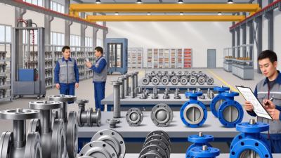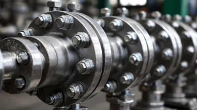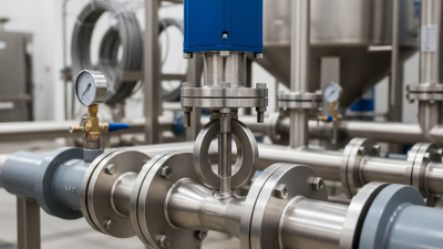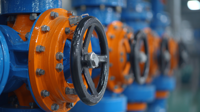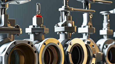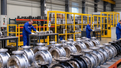
A butterfly valve is easy to recognize: a circular disc turns inside the pipe, opening or restricting the flow. A quarter-turn moves it from closed to open. The compact body can save space, while the disc remains in the flow path. That detail matters. In abrasive or viscous service, material choice and operating conditions deserve close attention.
Valve-selection author Peter Smith’s work offers a useful reminder: “A valve must be selected for the service, not just the pipe.” This is a practical summary, not a verified direct quotation. The point is important: pressure, temperature, fluid compatibility, and required shutoff performance all shape the choice. A butterfly valve that works well in a cooling-water line may not suit a process involving corrosive fluid or demanding isolation.
The main types include concentric, double-offset, and triple-offset designs. Concentric valves commonly use resilient seats and suit many general-purpose duties. Double-offset designs reduce seat friction during opening. Triple-offset versions use a metal seat and a cam-like sealing action for more demanding applications. There are trade-offs. A lower purchase price may mean more frequent maintenance, while a more specialized design can add cost and installation requirements.
Think of the pipe, too. A wafer-style body fits between flanges; a lug-style body can support separate bolting at each side. These differences affect maintenance and piping layout. This guide will explain how butterfly valves work, compare their types, and show which operating details to check before choosing one. Real systems vary, so manufacturer data and qualified engineering review remain essential.
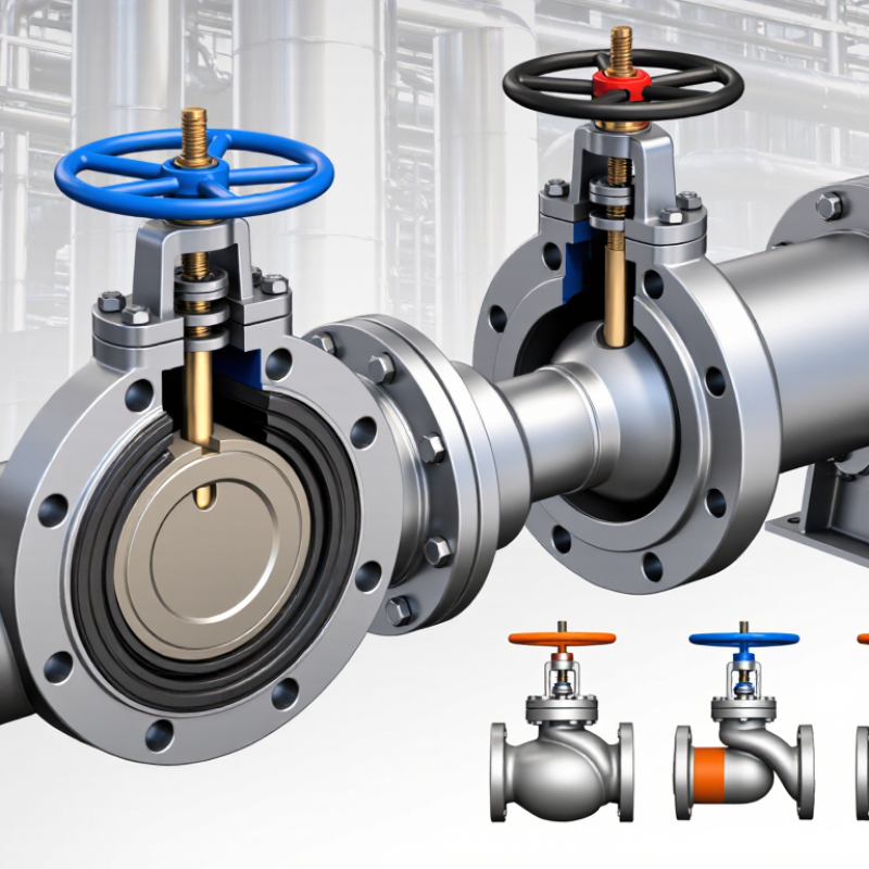
A butterfly valve controls flow with a circular disc mounted inside a pipe. The disc connects to a shaft and turns across the flow path. When its edge faces the flow, liquid or gas can pass through. A quarter turn. The disc swings across the passage to restrict flow or close the valve. Unlike a gate that lifts clear, the disc remains in the pipe.
In the open position, the disc sits roughly parallel to the flow. Turning the handle or actuator rotates the shaft, changing the disc’s angle. At a right angle, the disc blocks most of the passage, while a seat around its edge helps limit leakage. The valve is commonly used for isolation and flow adjustment, though its performance depends on design, materials, and operating conditions.
A neat diagram can make the action seem simpler than it is. Pressure, fluid speed, and seat wear can affect the force needed to turn the disc and how tightly it closes. The disc also interrupts flow even when fully open, which may create a pressure drop. In practice, choosing a valve means checking the pipe size, fluid, temperature, and expected pressure—not just the handle position.
A butterfly valve is built around a compact set of parts that work together to control flow. The body fits between or connects to pipe ends, while a circular disc sits inside the flow path. A stem runs through the body and links the disc to a handle, gearbox, or powered actuator. A quarter-turn moves the disc from open to closed. Simple in outline. Precise in fit.
The seat lines the body and helps form a seal when the disc closes. Seats may use resilient materials or metal, depending on temperature, pressure, fluid, and leakage requirements. The disc and stem also need suitable materials; corrosion and abrasion can affect their service life.
Body styles include wafer, lug, and flanged designs, each suited to different piping arrangements. In a wafer design, bolts commonly clamp the valve between pipe flanges. Lug designs provide threaded holes for bolting, while flanged bodies connect directly to matching flanges.
Alignment matters. A disc that rubs the seat unevenly may wear it faster or make operation harder.
Installation details can be easy to overlook, and a clean drawing does not guarantee a good fit in the field.
Check the valve’s specified pressure and temperature limits before selecting it.
A butterfly valve controls flow with a circular disc mounted inside the pipe. A quarter-turn of the stem moves the disc from parallel to the flow to nearly perpendicular. The opening changes quickly, so operators can isolate a line or adjust its flow. Picture a steel disc rotating within a pipe, leaving a narrow crescent-shaped passage when partly closed.
Disc position matters. At full opening, flow faces relatively little obstruction; at partial opening, the disc creates resistance and pressure loss. This makes butterfly valves useful for many water, HVAC, and process lines, but precise control depends on valve design, sizing, and operating conditions. Not every model handles throttling equally well. High flow speeds can also cause vibration, noise, or disc wear.
The U.S. Department of Energy’s Improving Pumping System Performance guide reports that pumping systems can consume 25–50% of energy in some industrial facilities. That range varies by site, but it shows why flow control deserves attention: throttling a valve can increase pumping demand. A well-sized valve and pump may reduce avoidable losses. The trade-off is easy to overlook. A valve that is partly closed all day may solve a control problem while quietly wasting energy.
| Type or Feature | Construction and Operation | How It Controls Flow | Common Uses | Key Considerations |
|---|---|---|---|---|
| Basic butterfly valve | A circular disc is mounted on a shaft inside the pipe. The shaft turns the disc, typically through about a quarter-turn between open and closed positions. | When open, the disc sits roughly parallel to the flow. Turning it toward a perpendicular position progressively restricts the passage; the disc and seat provide shutoff when closed. | Water distribution, HVAC systems, process piping, and other services where a compact quarter-turn valve is useful. | The disc remains in the flow path when open, creating some obstruction and pressure loss. |
| Concentric (resilient-seated) | The stem and disc are generally centered in the valve body. A resilient seat, commonly made from an elastomer, seals against the disc. | Disc rotation throttles flow, while the resilient seat provides shutoff. Its sealing performance depends on the seat material and service conditions. | Many water, air, and general-purpose services where operating conditions are compatible with the seat. | Seat material limits temperature and chemical compatibility; check the valve’s specified service ratings. |
| Double-offset (high-performance) | The stem is offset from the disc center and the pipe centerline. This geometry reduces rubbing between the disc and seat during much of the rotation. | The disc moves away from the seat as it opens and engages it near closure, supporting tighter shutoff and reduced seat wear compared with a basic concentric design. | Industrial process and utility applications that require higher performance than a typical resilient-seated valve can provide. | Seat design and materials vary; suitability depends on pressure, temperature, fluid, and leakage requirements. |
| Triple-offset (metal-seated) | Three offsets, including a conical seating geometry, help the metal sealing surfaces avoid rubbing except near the closed position. | The disc rotates clear of the seat through most of its travel and forms a metal-to-metal seal at closure. | Applications that may require metal seating, higher-temperature service, or demanding industrial shutoff performance. | Performance depends on design and installation; metal seating does not automatically mean zero leakage. |
| Wafer body style | The valve body fits between two pipe flanges and is held in place by flange bolts or studs. | Flow control comes from the rotating disc; the wafer description refers to the body connection, not a different disc-control mechanism. | Compact piping layouts where the valve is installed between flanges. | Check flange compatibility and piping requirements. A wafer valve may not provide the same end-of-line capability as a lug-style design. |
| Lug body style | The body has threaded lugs around its perimeter for bolting to pipe flanges. | Like other butterfly valves, it controls flow by rotating the disc. The lugs describe how the body connects to the piping. | Piping arrangements where bolting to each flange is required; some designs can support end-of-line service when specifically rated for it. | Verify the manufacturer’s design and pressure rating before using a lug valve with one side of the piping disconnected. |
| Flow-control practice | Manual levers, gear operators, or actuators position the disc. An actuator can be paired with a control system when automatic adjustment is needed. | Intermediate disc positions change the available flow area. The relationship between disc angle and flow is not necessarily linear. | On/off isolation and, where the valve is designed and sized for it, throttling or modulating service. | For stable control, consider the valve characteristic, pressure drop, flow range, and cavitation or noise risks. Do not assume every butterfly valve is suitable for throttling. |
| Selection note: Valve type, body style, seat material, and pressure class are separate selection factors. Confirm compatibility with the fluid, operating temperature, pressure, required shutoff, and applicable piping standards. | ||||
Common butterfly valves are often grouped by body style and disc design. Wafer valves fit between two pipe flanges and are held in place by the connecting bolts. They are compact and common in systems with limited space. Lug-style valves have threaded inserts around the body, allowing each side of the pipe connection to be secured separately. This can help when a downstream section needs removal, though the installation must match the valve’s pressure rating. Flanged valves bolt directly to matching pipe flanges and can be easier to align in larger or heavier service.
Disc design also affects sealing and wear. A concentric valve has a disc centered on the stem and body. Its resilient seat suits many general-purpose water and air applications. Double-offset designs shift the stem and disc geometry, reducing seat contact as the valve opens. This can lower wear in more demanding service. Triple-offset valves add a conical sealing arrangement and are commonly selected for high-temperature or metal-seated duties. Details matter. The best type depends on the fluid, pressure, temperature, pipe layout, and operating frequency. A familiar design is not automatically the right one; I would verify the seat material and shutoff requirements before specifying it.
A butterfly valve regulates flow with a rotating disc; a quarter-turn moves it from open to closed. Common designs include concentric, double-offset, and triple-offset valves. The right choice depends on pressure, temperature, fluid chemistry, and how often the valve operates. Ductile iron is common in water service, while stainless steel can suit more corrosive media. Seat materials also matter: an incompatible elastomer may swell, harden, or leak. Small detail, big consequence.
Applications range from water distribution and HVAC to process piping. The U.S. EPA’s 2023 Drinking Water Infrastructure Needs Survey and Assessment estimates $625 billion in drinking-water infrastructure needs over 20 years. That figure is not a valve-market forecast, but it highlights why reliable, maintainable components matter. Check the required pressure rating, shutoff performance, connection style, and actuator needs. A standard resilient-seat valve may be economical, yet unsuitable for high temperatures or demanding cycle service. Selection is rarely one-size-fits-all.
Tips: Match the seat and body materials to the actual fluid, not just its name. Confirm operating temperature and pressure with the manufacturer’s published data. If the valve will throttle flow, verify its control range; some designs perform poorly near the closed position. Allow space for disc clearance, too. That part is easy to miss.
These approximate upper service temperatures illustrate how seat material can influence valve selection. Actual limits depend on the specific material grade, pressure, fluid, and operating conditions; check the valve manufacturer's specifications for the intended application.