How to Choose a Flow Control Valve in 2026?
Choosing a flow control valve in 2026 requires more than comparing prices or connection sizes. The correct choice affects pressure stability, energy use, plant safety, and maintenance intervals. Grand View Research estimates that the global industrial valves market was worth approximately USD 78.6 billion in 2023. Its forecast also indicates continued growth through 2030, supported by water treatment, energy, chemical processing, and manufacturing projects. The market is expanding. Selection errors remain expensive.
Reliable decisions begin with operating details. Record the fluid, temperature, pressure, flow range, viscosity, corrosion risk, and required shutoff class. A valve handling clean water may fail quickly in abrasive slurry. A stainless-steel body may still need compatible trim and seals. Small details matter. IEC 60534 provides guidance for industrial-process control valves, while ASME B16.34 addresses pressure-temperature ratings and design requirements. API standards may apply to specific oil, gas, and pipeline services.
Independent research also supports the need for better water and process infrastructure. The United Nations World Water Development Report 2024 states that roughly 2.2 billion people lacked safely managed drinking water in 2022. This pressure encourages smarter pumping and treatment systems. However, market reports use different definitions, so their forecasts should not be treated as exact predictions. That limitation deserves attention. In practice, the best flow control valve balances controllability, material compatibility, lifecycle cost, inspection access, and available technical support. A cheaper valve can become the most expensive component after repeated leaks, unstable flow, or unplanned shutdowns.
Define Flow Requirements with Cv: 1 US gpm at 1 psi Differential
How to Choose a Flow Control Valve in 2026?
Define Flow Requirements with Cv: 1 US gpm at 1 psi Differential
Choosing a flow control valve begins with a measurable flow requirement, not the pipe diameter alone. Cv describes the water flow rate through a valve at a 1 psi pressure differential. One Cv equals 1 US gpm under these reference conditions. For water, the basic relationship is Cv = Q ÷ √ΔP. If the fluid has a different specific gravity, include that value in the calculation.
Measure the real operating range. Record minimum, normal, and maximum flow rates, along with upstream and downstream pressures. A valve sized only for peak flow may operate nearly closed during normal service. That can cause unstable control, noise, or unnecessary wear. In field work, I have seen a carefully calculated valve perform poorly because the available pressure changed with another process line. The calculation was correct, but the assumptions were incomplete.
Tips: Select a valve that operates near the middle of its controllable range. Check Cv at normal flow, not only at maximum flow. Confirm fluid temperature, viscosity, and specific gravity. Leave enough pressure drop for stable control, but avoid wasting energy. A quick spreadsheet helps, though it should not replace pressure measurements. I also recheck the result after installation, because actual piping resistance can differ from drawings. That step is easy to skip. It is also where many sizing decisions need honest revision.
How to Choose a Flow Control Valve in 2026? - Define Flow Requirements with Cv: 1 US gpm at 1 psi Differential
Liquid valve-sizing reference:
Cv is the number of US gallons per minute of water that pass through a valve at a pressure differential of 1 psi.
For liquids, use:
Cv = Q × √(SG ÷ ΔP)
where Q is flow in US gpm, SG is specific gravity relative to water, and ΔP is pressure drop in psi.
| Service example |
Fluid |
Required flow
(US gpm) |
Specific gravity
(SG) |
Design ΔP
(psi) |
Required Cv |
Preliminary target Cv
(1.2 × required Cv) |
Suitable valve characteristics |
| Baseline reference |
Water at approximately 20°C |
1.0 |
1.00 |
1.0 |
1.00 |
1.20 |
General liquid control; verify the minimum controllable flow. |
| Small cooling loop |
Water at approximately 20°C |
5.0 |
1.00 |
4.0 |
2.50 |
3.00 |
Equal-percentage trim is commonly used where system resistance changes with load. |
| Process-water branch |
Water at approximately 20°C |
10.0 |
1.00 |
9.0 |
3.33 |
4.00 |
Confirm that the selected valve does not impose excessive permanent pressure loss. |
| Low-viscosity oil service |
Light oil, SG 0.85 |
3.0 |
0.85 |
4.0 |
1.38 |
1.66 |
Check viscosity, temperature, sealing compatibility, and minimum operating torque. |
| Glycol heating loop |
Water-glycol mixture, SG 1.05 |
2.0 |
1.05 |
2.5 |
1.30 |
1.56 |
Account for concentration- and temperature-dependent viscosity before final selection. |
| High-pressure water branch |
Water at approximately 20°C |
20.0 |
1.00 |
16.0 |
5.00 |
6.00 |
Evaluate cavitation risk, flashing potential, noise, and valve pressure rating. |
Selection checkpoints:
Specify minimum, normal, and maximum flow; available inlet pressure; allowable outlet pressure; fluid temperature; viscosity; solids content; required shutoff performance; connection size; body and trim materials; actuator fail position; and control signal.
The preliminary target Cv is not a substitute for a final sizing check against the valve manufacturer's certified flow coefficients, cavitation limits, pressure class, and applicable safety requirements.
Select Valve Types for Liquids, Gases, and Two- or Three-Way Control
How to Choose a Flow Control Valve in 2026?
Choosing a flow control valve starts with the medium, not the pipe size. Liquids often require attention to viscosity, pressure drop, and cavitation risk. A sudden pressure fall can create vapor bubbles and damage internal surfaces. For gases, compressibility changes the calculation. Noise, temperature, and potential choking also deserve careful review. Record normal, minimum, and maximum flow rates before selecting a valve. Real operating data is more useful than a convenient estimate.
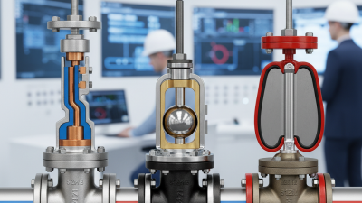
Two-way valves suit straightforward throttling or shutoff duties. They regulate flow through one inlet and one outlet. Three-way valves either mix two streams or divert one stream into separate paths. Mixing valves help maintain a stable outlet temperature. Diverting valves can route process fluid around equipment. The wrong arrangement may still fit physically, but it will control poorly.
Valve materials must match the fluid and temperature range. The actuator should provide enough force under the highest differential pressure. Consider the required failure position when power or air is lost. A qualified engineer should verify sizing with published flow coefficients and site conditions. I once saw a valve selected from average flow alone; it performed acceptably until seasonal demand changed. That mistake was avoidable. Perfect assumptions are rare. Leave room for uncertainty, testing, and future process changes.
Match Pressure and Temperature Ratings to ASME B16.34 Classes
How to Choose a Flow Control Valve in 2026?
ASME B16.34 classes are pressure-temperature ratings, not simple pressure labels.
A Class 600 valve may tolerate high pressure at ambient conditions, yet lose capacity as temperature rises. Check the applicable pressure-temperature table for the valve material group. Then compare the design pressure and design temperature, not only normal operating values. Include startup, shutdown, blocked outlets, thermal expansion, and credible upset conditions.
Material matters greatly.
Body, bonnet, trim, bolting, and sealing components must remain compatible with the service.
The U.S. Department of Energy’s Industrial Decarbonization Roadmap identifies process heat as roughly half of industrial energy demand. That keeps steam and high-temperature duties central to valve selection.
The International Energy Agency’s World Energy Investment 2024 report also projected global clean-energy investment above 2 trillion dollars, creating more demanding thermal cycles across industrial facilities.
Do not treat the class number as a guarantee.
Verify the exact material designation, temperature derating, end connection, and test requirements in ASME B16.34:2022. A pressure rating can look adequate on paper. Then a hot startup exposes the weakness.
I have seen specifications copy ambient ratings without checking operating temperature. That shortcut deserves review.
For severe cycling, calculate fatigue effects and confirm actuator torque at the coldest and hottest conditions. Leave practical margin, but avoid oversized selection that damages control accuracy.
Specify Shutoff Performance Using ISO 5208 Leakage Classes
How to Choose a Flow Control Valve in 2026?
Shutoff performance should be specified before valve size or actuator torque. A control valve may regulate accurately yet fail to isolate a line. ISO 5208:2015 defines leakage rates for pressure testing, using water or air under stated conditions. Class A represents the tightest commonly selected level, while other classes allow progressively higher leakage. Do not write “bubble-tight” without naming the test medium, pressure, duration, and seat direction. That phrase is too vague.
A practical specification might require ISO 5208 Class A for a toxic, sterile, or high-value process stream. Less critical utility service may accept a higher leakage class. Confirm the requirement with the process safety review. IEA’s Energy Efficiency 2024 report identifies industry as responsible for about 37% of global final energy consumption. Small leakage can therefore become a measurable operating cost across large facilities. The U.S. Department of Energy also recommends systematic steam-system assessments because failed isolation and passing valves can increase water, fuel, and maintenance losses. Check the numbers for your plant.
Valve selection should include seat material, differential pressure, temperature, and actuator fail position. Test certificates should identify the actual ISO 5208 rate, not simply state “tested.” That detail matters. A higher class may increase cost, torque, or maintenance sensitivity. Over-specifying can be wasteful. Under-specifying can be dangerous. The uncomfortable part is that the cheapest valve may only look cheaper before commissioning.