Choosing the right pneumatic actuator is not simply a matter of matching a cylinder to a valve. In real installations, small errors can create large problems. A valve may stall, move slowly, or fail to close completely. The correct selection begins with the application, not the product catalogue.
A pneumatic actuator converts compressed air into mechanical motion. Its required torque or thrust depends on valve type, load, friction, pressure, stroke, and operating speed. Butterfly and ball valves may need extra breakaway torque after long periods without movement. Check the complete torque curve, not only the average value. Then compare it with the actuator’s output at the actual air pressure. Leave a practical safety margin, but avoid excessive oversizing. It can increase cost, air consumption, and impact stress.
The operating environment also deserves close attention. Outdoor equipment may face rain, dust, salt, or freezing temperatures. Food and chemical applications often require suitable materials and certified protection. Confirm mounting dimensions, shaft compatibility, control-valve response, and available air quality. ISO 5211 interfaces can simplify valve mounting, but dimensions still need verification. Do not guess.
Experienced engineers also consider failure behavior. A spring-return pneumatic actuator may move the valve to a safer position during air loss, while a double-acting model may suit stable, repeated operation. Manufacturer data remains essential, yet field conditions can differ from laboratory ratings. That is where careful review matters. A sound choice balances performance, reliability, maintenance access, and total operating cost. There is no universal best actuator. The right one is the actuator that performs predictably in your specific system.
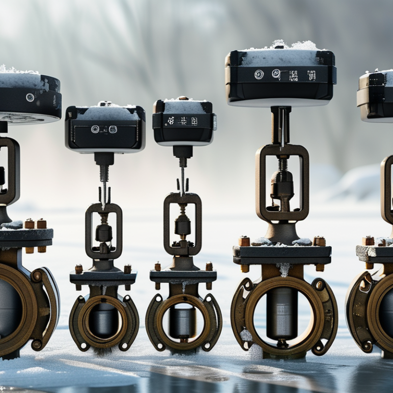
Choosing a pneumatic actuator starts with the machine, not the catalog. Describe the valve or mechanism it must move. Record required torque or thrust, rotation angle, stroke length, and cycle frequency. Measure these values under real load conditions. A clean, dry test bench can hide problems.
Air pressure is equally important. Identify the minimum and maximum supply pressure at the actuator inlet. Include pressure loss through filters, tubing, regulators, and control valves. Specify air quality, temperature range, humidity, and installation conditions. Dust, washdown water, or corrosive vapors may require different seals and enclosure protection. Do not estimate load from normal operation alone. Startup friction and occasional jams can demand much higher force.
Define the desired movement carefully. Is it simple open-and-close motion, or does it need controlled speed and intermediate positioning? Check whether the actuator must fail open, fail closed, or hold position during air loss. Calculate a suitable safety margin, but avoid excessive oversizing. A larger unit may consume more air and create damaging impact. Requirements are often incomplete. I have seen cycle counts recorded hourly, while maintenance needed them per minute. Recheck every assumption with measured data, drawings, and operator feedback. That small review can prevent a costly mismatch.
Selecting a pneumatic actuator starts with the machine’s movement, not its appearance. Linear actuators suit pushing, clamping, and lifting tasks. Rotary actuators handle turning valves, indexing tables, or positioning arms. A single-acting design uses air in one direction and a spring for return. A double-acting design uses air for both strokes and offers better control.
Measure the required force at the working point. Include friction, tooling weight, acceleration, and pressure losses. A cylinder lifting a 40-kilogram fixture may need far more than its calculated static load. Real machines vibrate, seals wear, and supply pressure can fluctuate. Add a practical safety margin, but avoid excessive oversizing. It increases air consumption and may create harsh impacts. Stroke length, cycle speed, and mounting alignment also matter. Poor alignment can damage the rod or guides.
Tips: Test the actuator under realistic conditions. Check force at the lowest available pressure, not the ideal pressure. For fast cycles, select cushioning carefully and verify the manufacturer’s speed limits. A smaller actuator may work beautifully in a clean laboratory, yet struggle beside metal dust and temperature changes. I have seen designs fail because the return spring was treated as a perfect constant. It is not. Review the load profile, air quality, and maintenance access before approving the final size. Leave room for adjustment. Even good calculations need field evidence.
How to Choose the Right Pneumatic Actuator?
Selecting a pneumatic actuator starts with the working environment, not the catalog image. In humid workshops, stainless steel or coated aluminum resists corrosion better than untreated surfaces. For dusty areas, choose sealed construction and protect the rod from abrasive particles. I have seen clean-looking cylinders fail early because moisture collected inside the air line.
Measure twice. Calculate the required force from load, pressure, friction, and safety margin. A vertical load needs extra capacity because gravity continues acting during every cycle. Bore size controls force, while stroke length determines movement distance. Do not select a larger actuator automatically. It may consume more air, move less smoothly, and increase operating costs. A smaller unit can also disappoint when pressure drops below its rated value.
Check operating specifications carefully. Confirm working pressure, temperature range, cycle speed, mounting position, and available installation space. Cushioning is useful when a piston stops heavily at the end of its stroke. Magnetic sensing may help confirm position, but sensors need clean mounting surfaces and correct alignment. Air is not free. Review air consumption per cycle, especially on equipment running thousands of times daily. I once focused only on peak force and ignored response speed. That choice worked on paper, but not on the production floor. Verify calculations with actual load tests, because friction and imperfect alignment often resist neat assumptions.
Select the actuator by matching its material, bore size, stroke, operating pressure, temperature, and environmental requirements. The chart below shows the theoretical extension force produced by common bore sizes at typical supply pressures.
Selection guidance: Aluminum actuators are lightweight and suitable for general industrial applications. Stainless steel is preferred in wet, corrosive, or washdown environments. Choose a larger bore when higher force is required, and allow additional capacity for friction, load variation, and safety margin. The values shown are theoretical extension forces calculated using F = P × A and do not include friction losses.
Choosing the right pneumatic actuator starts with the valve, not the actuator catalogue. Confirm the valve type, shaft pattern, rotation angle, and required breakaway torque. A butterfly valve may need a different torque profile from a ball valve. Use tested valve data, then add a sensible safety margin. Too little torque causes incomplete travel. Too much may damage the stem or seat. I have seen sizing based only on running torque. It looked acceptable on paper, yet the valve stalled after a long shutdown.
The control system must match the actuator’s operating method. Check whether it needs single-acting or double-acting control. Verify the solenoid valve’s port size, voltage, and flow capacity. Confirm that feedback switches suit the available input signals. Mechanical clearance matters too. A compact assembly may block wiring access or manual override operation. Air supply deserves equal attention. Confirm pressure, flow, tubing length, and compressor capacity during peak demand. Use clean, dry air with suitable filtration. Pressure drops at distant stations can make a correctly sized actuator behave poorly. Measure pressure at the actuator, not only at the compressor gauge.
Tips: Before installation, cycle the valve several times at the lowest expected pressure. Record opening time, closing time, and end-position signals. Check for leaks using an approved method. Recheck fasteners after initial operation. A short test can expose incorrect rotation or weak air supply. Do not assume the first result is enough.
How to Choose the Right Pneumatic Actuator?
Evaluate installation, maintenance, safety, and total cost before comparing purchase prices. Start with mounting space, stroke length, load, air pressure, and cycle speed. A practical commissioning lesson is simple: a correctly sized actuator can still fail when tubing bends sharply or exhaust air has no clear path. Measure real operating pressure, not only the compressor’s nameplate rating. Include brackets, valves, sensors, tubing, and installation labor in the calculation.
Tips: Check the actuator at its slowest cycle. Inspect seals after the first month. Keep a spare seal kit nearby. The U.S. Department of Energy’s Compressed Air Challenge sourcebook reports that compressed air may consume about 10% of industrial electricity. It also identifies leaks as a frequent source of wasted capacity. Therefore, choose efficient controls and schedule leak inspections, rather than buying oversized equipment. Oversizing feels safer, but it can increase air use and impact response.
Maintenance access matters. A removable actuator may reduce downtime, even when its purchase price is higher. Use guarding, pressure isolation, and controlled exhaust in line with ISO 4414 safety principles. Confirm that maintenance workers can lock out the air supply without reaching across moving parts. Total cost should include energy, replacement seals, inspection time, and unplanned stoppages. This calculation is imperfect. Yet it is more reliable than judging equipment by its catalog price alone.
| Evaluation Dimension | Single-Acting Spring-Return | Double-Acting Rack-and-Pinion | Double-Acting Scotch-Yoke | Selection Guidance |
|---|---|---|---|---|
| Typical valve applications | On/off service where the valve must move to a defined position after loss of air. | Quarter-turn ball, butterfly, and plug valves requiring reliable powered opening and closing. | Large or high-torque quarter-turn valves, especially when breakaway torque is significant. | Match the actuator output torque to the valve torque curve, not only to the valve size. |
| Installation space | Usually requires additional length for springs; check overall envelope and spring-module access. | Compact and symmetrical; generally suitable where mounting space is limited. | Often larger and heavier at higher torque outputs; allow room for support and maintenance access. | Verify mounting standard, shaft height, orientation, tubing clearance, and access for manual override. |
| Operating pressure | Commonly designed for compressed air around 4–8 bar, subject to the selected model and spring package. | Commonly designed for compressed air around 4–8 bar, subject to the selected model and operating limits. | Commonly designed for compressed air around 4–8 bar, with model-specific pressure limits. | Select using the minimum available pressure, including regulator losses and pressure drops. |
| Fail position and safety | Provides spring-to-close or spring-to-open action when correctly configured. | Requires a separate fail-action solution, such as a spring module or another approved energy-storage device. | Requires a separate fail-action solution and careful assessment of stored mechanical energy. | Define the safe valve position after loss of air, power, signal, or control system function. |
| Torque characteristics | Output torque changes as the spring is compressed or released; confirm both air and spring torque. | Generally provides a balanced torque profile for many quarter-turn valves, but valve breakaway torque must still be checked. | Typically delivers high breakaway torque near the start and end of rotation, which can suit demanding valves. | Include packing friction, differential pressure, seat load, temperature, and a documented safety factor. |
| Speed adjustment | Usually adjusted with flow-control valves; exhaust restriction can affect fail-action time. | Usually easy to adjust with meter-out flow controls, provided the control valve is correctly sized. | Speed can be adjusted, but the larger moving mass may require careful cushioning and commissioning. | Confirm required opening and closing times and avoid excessive speed that may cause water hammer or valve damage. |
| Maintenance requirements | Inspect springs, seals, fasteners, position indicators, and air connections; spring replacement requires controlled procedures. | Inspect seals, bearings, pinions, racks, fasteners, and lubrication condition according to the maintenance schedule. | Inspect yoke surfaces, sliding blocks, bearings, seals, fasteners, and lubrication condition. | Use clean, dry air and schedule inspection based on cycle count, environment, and consequence of failure. |
| Air consumption | Can be lower in some cycles because the spring provides one direction of movement, but the air volume depends on size and stroke. | Consumes air for both directions; total use depends on actuator volume, pressure, cycle frequency, and leakage. | Often has larger internal volume at high torque, which can increase air demand per cycle. | Estimate annual air consumption from actual cycles and compressor energy cost rather than purchase price alone. |
| Environmental suitability | Suitable for many industrial environments when materials, coatings, seals, and temperature ratings are correctly selected. | Suitable for general industrial service; corrosion protection and enclosure ratings are required for harsh environments. | Suitable for demanding service when heavy-duty construction and appropriate protection are specified. | Check ambient temperature, humidity, dust, corrosive chemicals, hazardous-area requirements, and washdown exposure. |
| Initial cost factors | Actuator, spring package, solenoid valve, air preparation, mounting kit, and safety accessories. | Actuator, solenoid valve, air preparation, mounting kit, position feedback, and optional fail-action equipment. | Larger actuator, structural support, mounting hardware, control components, and possible lifting equipment. | Compare the complete installed package, including controls, wiring, tubing, supports, testing, and commissioning. |
| Total cost of ownership | May reduce control complexity but can have spring replacement and fail-action testing costs. | Often economical for frequent cycling when air use, seal life, and spare-part availability are well managed. | May justify higher purchase and installation cost where high torque and long service life reduce downtime risk. | Include energy, preventive maintenance, spare parts, downtime, safety testing, disposal, and expected service life. |
| Best-fit profile | Safety-critical on/off duties needing a defined fail position and moderate torque. | General-purpose automated quarter-turn valves with frequent operation and limited installation space. | High-torque, large-valve, or high-friction applications where torque delivery is a primary concern. | Choose only after confirming valve torque, cycle time, air quality, safety function, environment, and lifecycle economics. |
Note: Values and recommendations are typical engineering considerations. Final sizing must be based on the valve manufacturer’s torque data, actuator performance data, applicable safety requirements, and site conditions.