
Blog
What Are the Top 10 Types of Electric Valve Actuators?
Electric valve actuators turn electrical power into the movement that opens, closes, or positions a valve. At a water-treatment plant, one may rotate a butterfly valve beside a damp pump room. Elsewhere, a linear unit may move a globe valve along a process line. The application changes the demands.
That is why “top” should not mean universally best. This guide compares ten common actuator types and configurations, including multi-turn, quarter-turn, linear, on/off, and modulating designs. It also considers control method, torque or thrust, operating cycle, power supply, enclosure, and feedback. Small details matter. A tight installation space, frequent starts, or a need for precise positioning can change the choice.
Selection begins with the valve, not the product label. Check required torque or thrust, travel, duty cycle, ambient conditions, and whether the actuator must hold position after power loss. Then verify compatibility with the valve stem, controls, and available supply. Manufacturer data sheets and qualified engineering review are useful; a catalog rating alone may not reflect real service. The categories can overlap, so any top-ten list is a practical map, not a strict ranking. Some distinctions are less tidy than they appear. The comparisons ahead explain where each type fits, what trade-offs to inspect, and which questions to ask before specification. That modest caution helps.
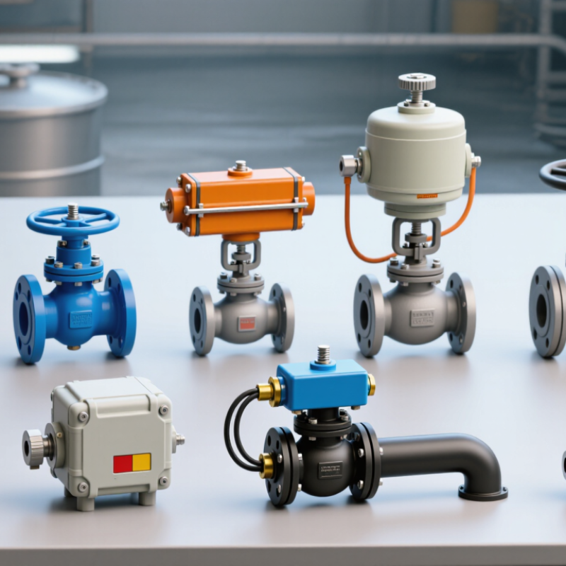
How Electric Valve Actuators Work and How They Are Classified
An electric valve actuator turns electrical energy into controlled valve movement. A motor drives gears, which increase torque or reduce speed. The output then rotates a valve stem or pushes it in a straight line. Small movements matter. In practice, wiring, valve friction, and fluid pressure can all affect positioning. A control signal may simply open or close the valve, or adjust it gradually. Sensors can report position to a controller, helping operators spot a mismatch between the command and the valve’s actual position.
Classification depends on the feature being considered, so the types can overlap. By motion, common designs include quarter-turn, multi-turn, and linear actuators. By control, they include on-off and modulating types. Other useful categories include smart, compact, high-torque, spring-return, and battery-powered actuators. That gives ten labels, but they are not ten mutually exclusive designs: a compact actuator may also be quarter-turn and modulating. Selection should match the valve’s required travel, torque, duty cycle, and control method. A small sizing error can leave a valve slow or unable to seat fully. Checking real operating conditions is wise; catalog figures alone may not tell the whole story.
What Are the Top 10 Types of Electric Valve Actuators? — How Electric Valve Actuators Work and How They Are Classified
Electric valve actuators use an electric motor and a transmission mechanism to move a valve. The categories below describe common actuator designs and classifications; some can be combined in one unit.
| Type | How It Works | Typical Valve Movement | Common Valve Examples | Typical Uses and Selection Notes |
|---|---|---|---|---|
| 1. Multi-turn actuator | A motor and reduction gearing rotate an output drive through multiple turns. A stem nut or related drive transfers this rotation to the valve stem. | Several turns of the output; may produce linear stem travel in a rising-stem valve. | Gate valves, globe valves, and some rising-stem valves. | Used where a valve needs multiple stem turns to open or close. Thrust and stem-interface requirements must match the valve. |
| 2. Part-turn (quarter-turn) actuator | A geared motor rotates the output through a limited angle, commonly about 90 degrees, between end positions. | Limited-angle rotation, usually a quarter turn. | Butterfly valves, ball valves, and plug valves. | Often selected for fast, compact operation of rotary valves. Required torque can vary substantially with valve size and operating conditions. |
| 3. Linear actuator | A motor drives a screw, nut, or comparable mechanism to create straight-line output motion. | Linear extension and retraction. | Globe control valves, pinch valves, and some diaphragm valves. | Suitable when the valve stem moves in a straight line. Check the required stroke, thrust, and mounting arrangement. |
| 4. Direct-drive rotary actuator | The motor turns the valve output directly or through minimal gearing, reducing the number of transmission components. | Rotary, commonly limited-angle movement. | Small ball valves and compact butterfly valves. | Can provide a compact assembly, but the motor must deliver sufficient torque across the valve’s operating range. |
| 5. Geared rotary actuator | A reduction gearbox lowers motor speed and increases output torque before transmitting motion to the valve. | Part-turn or multi-turn rotation, depending on the gearbox and output design. | Large butterfly valves, ball valves, and other high-torque rotary valves. | Useful when the valve requires more torque than a direct-drive arrangement can provide. Gear ratio affects output speed and operating time. |
| 6. On/off actuator | Control inputs drive the actuator toward an open or closed end position; limit switches or position sensing can indicate travel limits. | Movement between defined end positions. | Isolation ball, butterfly, gate, and plug valves. | Common for isolation and sequencing duties. It is not intended to continuously regulate flow unless specifically designed for that service. |
| 7. Modulating actuator | A position-control system adjusts motor operation in response to a command and feedback signal, allowing intermediate positions. | Continuous or incremental positioning across the operating range. | Control globe valves, characterized ball valves, and control butterfly valves. | Used for flow, pressure, or temperature control. Positioning accuracy and response depend on the actuator, valve, control signal, and system setup. |
| 8. Fail-safe electric actuator | An integrated energy reserve, such as a battery or capacitor, or another specified mechanism moves the valve to a preset position when normal power is lost. | Typically moves to a defined safe position, such as open or closed, on loss of power. | Quarter-turn and linear valves in safety or process-control duties. | Provides a specified response to power failure. The required fail position, available stored energy, valve load, and operating conditions must be verified. |
| 9. Explosion-protected actuator | An electrical enclosure and design features are selected and certified for use in the applicable hazardous-area classification. | May be multi-turn, part-turn, or linear; the hazardous-area protection is an enclosure and equipment classification. | Process valves in classified areas where flammable gas, vapor, or dust may be present. | Selection must follow the site’s area classification and applicable certification requirements. This describes protection, not a distinct motion type. |
| 10. Submersible or weatherproof actuator | Seals, enclosure design, and cable or connection arrangements protect the actuator against specified water or environmental exposure. | May be multi-turn, part-turn, or linear, depending on the valve. | Water-treatment, outdoor, and flood-exposed valve installations. | Protection is defined by the rated enclosure and installation conditions. Confirm the required ingress protection and any limits on immersion depth or duration. |
Related Posts
-
How to Choose Electric Valve Actuators for Your Project?
-
China Top Actuator Valve Manufacturers for Global Buyers
-

2026 How to Choose the Right Actuator Valve for Your Needs?
-
China Top Motorized Valve Manufacturers How to Choose?
-
China Best Actuator Valve Manufacturers How to Choose?
-
How to Choose the Right Pneumatic Flow Control Valve for Your Needs?