
Blog
7 Tips for Choosing the Right Pneumatic Rotary Actuator
Selecting the right pneumatic rotary actuator can determine whether a machine runs smoothly or struggles under pressure. In practice, small specification errors often create large maintenance problems. A unit may rotate correctly in testing, then stall when a valve, damper, or gripper meets real resistance. This guide explains seven practical tips for making a more reliable choice.
The process begins with the application, not the product catalogue. Check required torque, rotation angle, operating pressure, speed, cycle frequency, and available space. Consider the load’s inertia and any friction caused by seals or deposits. A pneumatic rotary actuator should provide enough torque without becoming unnecessarily oversized. Oversizing can increase air consumption and slow response. Undersizing is worse.
Material selection also matters. Aluminum bodies suit many indoor systems, while stainless steel may perform better near moisture or corrosive cleaning agents. Confirm shaft dimensions, mounting patterns, cushioning options, and sensor compatibility. Review manufacturer data carefully, and compare tested performance rather than attractive headline figures. A neat spreadsheet can still mislead.
Real installations deserve attention. Dust, temperature changes, poor lubrication, and unstable air pressure can shorten service life. Experienced engineers often leave a practical safety margin, but the margin should have a reason. More is not always safer. I have seen teams focus on peak torque while overlooking frequent cycling and end-position shock. That mistake was expensive.
Reliable decisions also require traceable evidence. Ask for torque curves, operating limits, material details, and maintenance guidance. Check whether the supplier offers technical support and replacement parts. When uncertain, test the actuator with the actual load. Laboratory assumptions rarely capture every installation detail. These seven tips will help connect engineering calculations with dependable performance, though careful review remains essential.
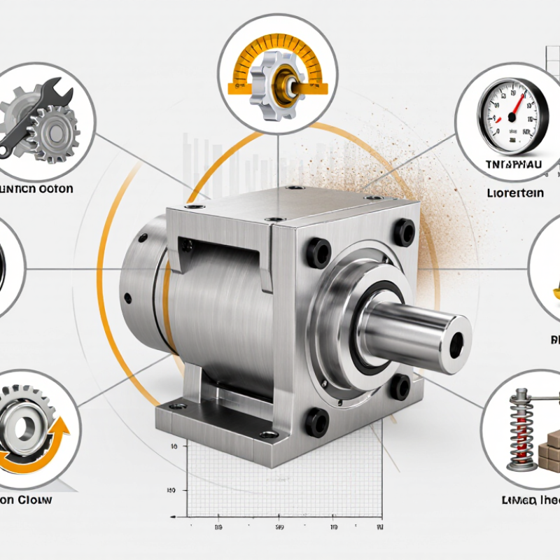
Understanding Pneumatic Rotary Actuator Types and Operating Principles
Choosing the right pneumatic rotary actuator starts with its operating principle. Rack-and-pinion models convert piston movement into rotation through meshing gears. They suit common quarter-turn valves and provide consistent torque. Vane actuators use air pressure against a rotating vane inside a sealed chamber. They are compact, but their torque range may be more limited. Scotch-yoke designs can deliver higher breakaway torque, especially during valve opening.
Check whether the application needs double-acting or spring-return operation. A double-acting actuator uses compressed air for both directions, offering controlled movement. A spring-return unit uses air in one direction and springs in the other. It can move to a safer position during air loss. Confirm the required rotation angle, usually 90 degrees, before selecting the body size. Measure valve torque at startup, not only during steady movement. Add a practical safety margin, but avoid excessive sizing.
Air pressure, cycle speed, temperature, and mounting space also affect performance. Install cushioning when a heavy load stops sharply. It reduces impact near the rotation limit. Inspect the air supply for water, oil contamination, and unstable pressure. These details often decide service life. I have seen selections fail because engineers trusted nominal torque figures alone. That approach is convenient, but incomplete. Test the actuator with the actual valve, fittings, and control accessories when possible. Real resistance can differ from laboratory data. Check shaft alignment and fastener access before commissioning; small installation errors can create uneven wear.
| Selection Tip | Actuator Type | Operating Principle | Typical Rotation | Key Selection Data | Advantages | Important Limitations | Suitable Applications |
|---|---|---|---|---|---|---|---|
| 1 Match the required motion | Rack-and-pinion rotary actuator | Compressed air moves one or two pistons. The pistons drive a rack that turns a pinion shaft, converting linear piston motion into rotary motion. | Usually 90° or 180°; other angles may be available through adjustable stops. | Confirm the required angle, rotation direction, cycle rate, and whether the application needs single or double acting operation. | Compact design, repeatable angular movement, broad torque range, and easy integration with pneumatic valves. | Torque can vary during the stroke; external loads should not exceed the specified shaft, bearing, or side-load capacity. | Quarter-turn valves, clamps, indexing devices, diverters, and material-handling mechanisms. |
| 2 Choose torque with a safety margin | Vane-type rotary actuator | Compressed air acts on one or both sides of a vane attached to a central shaft, producing direct rotary motion inside a housing. | Commonly 90° to 270°, depending on the internal stop arrangement. | Calculate load torque, friction torque, acceleration torque, and breakaway torque. Select a rated torque above the calculated requirement, commonly with a practical margin of approximately 25% to 50%. | Low part count, smooth movement, compact envelope, and wide angular travel in some designs. | Usually offers less torque multiplication than a comparable rack-and-pinion design and may be more sensitive to seal wear or contamination. | Light-duty positioning, small dampers, laboratory equipment, compact automation, and low-inertia mechanisms. |
| 3 Select the correct operating mode | Double-acting actuator | Air pressure is supplied alternately to both sides of the piston or vane to drive the shaft in both directions. | Typically 90° or 180°, with adjustable end stops on many models. | Check available supply pressure, valve configuration, required return speed, and torque in both directions. | Positive control in both directions, consistent cycling, and adjustable speed using flow-control valves. | The actuator generally requires compressed air to move to its fail position; loss of air may leave the load in an undesirable position. | Automated valves, pick-and-place equipment, indexing tables, and applications requiring powered return motion. |
| 4 Define the required fail-safe action | Single-acting actuator | Air pressure drives the shaft in one direction, while a spring returns it when the air supply is removed. | Most often 90° or 180°. | Specify the required fail-open or fail-closed position, spring-return torque, available air pressure, and the number of cycles expected. | Provides a predictable return position during air or control failure and can improve process safety. | Spring force reduces the available powered torque and may increase actuator size, energy use, and wear compared with a double-acting design. | Emergency shutoff valves, ventilation dampers, fuel or process isolation, and safety-related control functions. |
| 5 Verify air-pressure compatibility | Pneumatic rotary actuator with position control | A directional control valve regulates airflow to the actuator. Flow controls, positioners, sensors, or proportional valves can be added to manage speed and angular position. | Commonly 0° to 90° or 0° to 180°; intermediate positioning depends on the control system. | Verify the actuator torque at the actual working pressure, not only at the maximum rated pressure. Many industrial systems operate near 5 to 7 bar gauge, but the manufacturer’s rating must be followed. | Fast response, simple pneumatic energy storage, and effective speed control when air preparation and metering are correctly designed. | Air compressibility can reduce precise positioning performance; pressure fluctuations, leakage, and poor flow control can affect repeatability. | Damping systems, variable-angle positioning, process control, packaging, and synchronized automation. |
| 6 Check environmental and mounting requirements | Heavy-duty rack-and-pinion actuator | Larger pistons generate linear force, while racks and pinions convert that force into shaft torque. Multiple stages may be used for higher output torque. | Usually 90° or 180°, with mechanical end-stop adjustment often available. | Check ambient temperature, humidity, dust, corrosive chemicals, washdown exposure, mounting orientation, shaft loading, and enclosure or ingress-protection requirements. | High torque capability, durable construction, and suitability for demanding industrial valve and automation service. | Larger size, higher air consumption, greater mass, and potentially higher cost than compact actuators. | Large process valves, industrial dampers, bulk-handling equipment, and high-cycle production machinery. |
| 7 Review life, maintenance, and total operating cost | Compact rotary actuator | A small vane or piston mechanism produces limited-angle shaft rotation, normally using a simple two-position or three-position pneumatic circuit. | Commonly 90°; some designs provide 180° or adjustable travel. | Compare cycle life, lubrication requirements, seal material, air consumption, switching frequency, noise, spare-part availability, and ease of mounting. | Small footprint, low weight, fast installation, and reduced air consumption for low-load applications. | Limited output torque and lower tolerance for excessive inertia, shock loads, side loads, or incorrect end-stop adjustment. | Small grippers, sorting mechanisms, laboratory automation, compact conveyors, and light-duty assembly equipment. |
Related Posts
-
China Best Actuator Valve Manufacturers How to Choose?
-
How to Choose the Right Pneumatic Actuator?
-
China Top Pneumatic Valve Actuator Manufacturers?
-

How to Choose the Right Pneumatic Actuator for Your Needs?
-

Top Motorized Valves for 2025 Which One is Right for Your Needs
-
What is a Duplex Basket Strainer and How Does It Work?