
Blog
10 Best Pneumatic Butterfly Valves for Industrial Buyers
Choosing a pneumatic butterfly valve is not just a matter of matching pipe diameter. The actuator must deliver enough torque to move the disc against real operating pressure, not just ideal catalog conditions. A valve that works smoothly on a clean water line may behave differently with abrasive slurry, sticky process media, or frequent cycling. Small details matter.
This guide to the 10 best pneumatic butterfly valves for industrial buyers focuses on the factors that shape dependable service. It considers body and disc materials, seat compatibility, pressure and temperature limits, actuator sizing, mounting standards, and available fail-safe options. For example, an EPDM seat may suit some water applications, while other media call for a different elastomer. Always verify compatibility with the manufacturer’s technical documentation.
Buyers should also look beyond the purchase price. Check air-supply requirements, cycle life, spare-part availability, and access for maintenance around the installed valve. A compact actuator can save space, but only if it provides suitable torque across the full operating range. That matters. No shortlist can replace an application review, and product rankings may change with service conditions or regional support. Before selecting a model, compare its published specifications with your process data and ask the supplier to confirm sizing. It is an easy step to overlook. A careful match can reduce avoidable downtime and make routine operation more predictable.
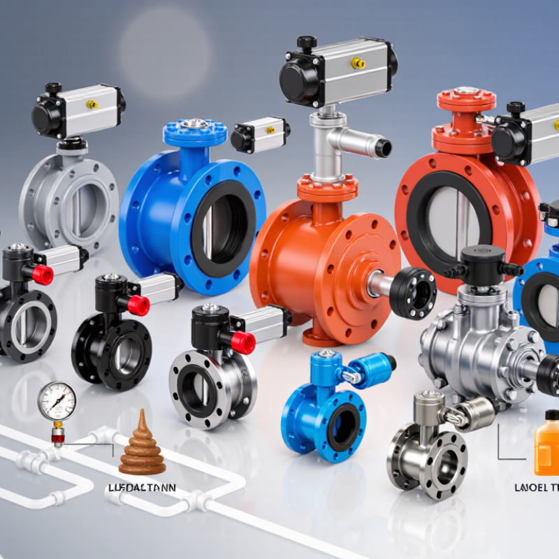
What Pneumatic Butterfly Valves Are and How They Work
A pneumatic butterfly valve uses compressed air to rotate a circular disc inside a pipe. The actuator turns the stem about 90 degrees, moving the disc between open and closed positions. At full flow, the disc remains in the stream, so pressure loss and clearance deserve attention. That matters. For throttling, a positioner can adjust the disc angle, but this valve may not control every fluid equally well. Abrasive solids, high velocity, and seat material can affect wear and shutoff performance.
The U.S. Department of Energy’s Improving Compressed Air System Performance sourcebook estimates that compressed air uses about 10% of industrial electricity. This is a system-wide estimate, not a valve-efficiency rating. Leaks and oversized actuators can waste air. Check required torque against worst-case pressure and temperature, not just clean, dry bench conditions. A small mismatch can cause sticking. Test it cold. Real installations are not always as tidy as diagrams suggest; actuator supply pressure can fluctuate.
Tips: Confirm disc clearance, fail position, and air-supply quality before installation. Cycle the valve under expected process conditions, then inspect seat and stem wear at scheduled intervals. If flow control is critical, test the operating range rather than assuming a quarter-turn produces linear flow.
10 Best Pneumatic Butterfly Valves for Industrial Buyers - What Pneumatic Butterfly Valves Are and How They Work
A pneumatic butterfly valve uses a compressed-air actuator to rotate a disc about a quarter-turn between open and closed positions. Double-acting actuators use air to move in both directions; spring-return actuators use air in one direction and a spring for the other. The options below are common valve configurations for different duties, not brand-specific products.
| No. | Valve type / best-fit duty | Typical construction and connection | Typical applications | Pneumatic and buyer considerations |
|---|---|---|---|---|
| 1 | Wafer, concentric, resilient-seated | Centered disc and stem; elastomer seat; wafer body fits between pipe flanges. | Water, HVAC, and general utility services where the specified pressure and temperature are within the valve rating. | Compact and commonly used for on/off control. Check flange compatibility, seat material, shutoff requirements, and whether the actuator has the required torque. |
| 2 | Lug, concentric, resilient-seated | Centered disc and elastomer seat; threaded lugs allow bolting to mating flanges. | Water and utility lines where end-of-line removal or a lug-style connection is useful. | Do not assume dead-end service is permitted: confirm the manufacturer’s rating for the intended pressure, direction, and removal of downstream piping. |
| 3 | Flanged, concentric, resilient-seated | Centered disc and elastomer seat; integral flanged ends connect directly to matching pipe flanges. | Water treatment, distribution, and process utility lines where a flanged body is specified. | Check flange drilling and facing, seat compatibility, installation space, and the valve’s rated pressure and temperature. |
| 4 | Double-offset, soft-seated, high-performance | Offset stem and disc geometry; commonly uses a polymer seat such as PTFE or reinforced PTFE; wafer, lug, or flanged bodies may be available. | Process services requiring tighter shutoff or higher operating capability than a basic concentric design can provide. | Confirm media compatibility and the specified leakage class. Select actuator torque using the valve data for the actual differential pressure and operating conditions. |
| 5 | Double-offset, metal-seated | Offset geometry with metal sealing surfaces; body and disc materials depend on the service and design. | Process duties where a soft seat may not suit the required temperature, wear, or media conditions. | Metal seating does not automatically mean zero leakage. Verify the required leakage class, material pairing, temperature rating, and actuator torque. |
| 6 | Triple-offset, metal-seated | Three-offset geometry with a cam-like, non-rubbing seating action; generally uses a metal seat and disc sealing surface. | Higher-temperature or demanding process duties when the selected design is rated for the service. | Check the specified leakage performance, pressure-temperature limits, materials, and cycle requirements. Do not infer suitability from the “triple-offset” description alone. |
| 7 | Fluoropolymer-lined butterfly valve | Corrosion-resistant lining, often PTFE or another specified fluoropolymer, isolates wetted areas from the process fluid. | Selected corrosive chemical services where the lining and exposed components are chemically compatible. | Check compatibility at the actual concentration and temperature, permeation or vacuum limitations, and which internal parts contact the media. |
| 8 | Sanitary butterfly valve | Cleanable, polished wetted surfaces and hygienic connections; wetted materials and elastomers are selected for the process. | Food, beverage, and pharmaceutical systems where hygienic design and cleaning procedures are required. | Confirm the required surface finish, connection standard, elastomer compliance, clean-in-place or sterilization conditions, and any applicable certifications. |
| 9 | Grooved-end butterfly valve | Grooved ends connect to compatible grooved pipe couplings; resilient-seated designs are common in water services. | Building services and water lines designed around grooved piping systems. | Match the groove profile and coupling system. For fire-protection use, verify that the complete valve and actuator assembly has the approvals required by the project. |
| 10 | Low-pressure air or gas butterfly valve | Often a lightweight wafer-style or damper-style design; seat and disc construction vary with the gas and duty. | Ventilation, exhaust, and other low-pressure air or gas duties when the valve is designed and rated for that service. | Check leakage requirements, gas compatibility, pressure drop, temperature, and whether the design is suitable for isolation rather than flow regulation. |
Ratings and performance vary by design, size, materials, and manufacturer. Before selection, confirm the operating pressure and temperature, media compatibility, required leakage class, connection standard, cycle frequency, and actuator fail position. Use published valve and actuator sizing data for the actual service conditions.
Related Posts
-
What Are the Top 10 Pneumatic Butterfly Valve Types?
-
2026 Top Pneumatic Butterfly Valve Manufacturers
-
2026 Best Pneumatic Butterfly Valve Types for Global Buyers
-
Understanding the Benefits of Basket Strainers in Industrial Applications
-
Top Motorized Valves for 2025 Which One is Right for Your Needs
-
How to Choose a Duplex Basket Strainer?