Blog

How to Choose a Pneumatic Valve Actuator?

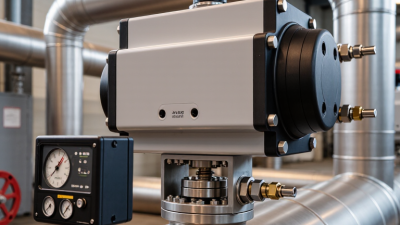
Choosing a pneumatic valve actuator is not a matter of matching pipe size with actuator size. It is a practical engineering decision involving torque, air pressure, valve design, cycle frequency, and operating conditions. A compact butterfly valve may require modest torque today, yet corrosion, packing friction, or hardened media can change that requirement tomorrow.

R. W. Zappe, author of Valve Selection Handbook, emphasizes, “The actuator must be selected to provide the required torque under all operating conditions.” That principle remains useful because real plants rarely behave like clean catalog examples. A reliable selection process examines breakaway torque, running torque, seating torque, and the manufacturer’s safety margin. It also checks whether the available instrument air can deliver full movement during pressure drops.

Look beyond torque.

The required fail position matters too. A spring-return pneumatic valve actuator may move the valve closed or open when air fails. Double-acting models can provide stronger, more consistent movement, but they need a suitable emergency strategy. Temperature, moisture, hazardous-area classification, mounting orientation, and control accessories also influence the final choice. Do not treat a generous safety factor as a substitute for accurate data. Excessive sizing can create sluggish control, unnecessary air consumption, and mechanical stress. That is an easy mistake.

This guide explains how to compare actuator types, calculate operating torque, verify air requirements, and confirm compatibility with the valve and control system. It also highlights the uncomfortable gaps: incomplete plant records, changing friction, and assumptions that nobody rechecks. Good selection is careful, evidence-based, and willing to revise itself.
How to Choose a Pneumatic Valve Actuator?

Identify the Valve’s Operating Requirements

How to Choose a Pneumatic Valve Actuator?

Identify the Valve’s Operating Requirements

Start with the valve, not the actuator. Record the valve type, size, pressure rating, medium, and operating temperature. A valve handling abrasive slurry may need more torque than a clean water valve of the same size. Measure it twice. Small details matter.

Determine the required torque throughout the complete stroke. Some valves demand peak torque during breakaway, while others need steady torque during travel. Include friction, pressure effects, and a reasonable safety margin. Avoid adding an excessive margin, because it can slow response and increase air consumption. A neat calculation can still mislead when actual packing friction is unknown.

Define the operating pattern clearly. Note the required opening time, closing time, cycles per hour, and expected service life. Check whether the valve must fail open, fail closed, or remain in its last position during air loss. Confirm the available air pressure and air quality, including moisture, oil, and particles. Dirty air can shorten actuator life.

The installation environment also affects selection. Consider outdoor exposure, corrosive vapors, dust, vibration, and limited space around the valve. Verify mounting orientation and accessory clearance before ordering. In field work, overlooked clearance has caused more delays than difficult calculations. I would also confirm emergency actions with the process engineer, because a technically correct actuator may create an unsafe response.

Match Actuator Type to Valve Design

How to Choose a Pneumatic Valve Actuator?

Match the actuator to the valve design, not just the pipeline size. Quarter-turn valves, such as ball, butterfly, and plug valves, usually require rotary actuators. Rack-and-pinion models suit many standard applications with steady torque. Scotch-yoke designs can provide higher breakaway torque for demanding valves. Check the valve’s opening and closing torque first. Running torque alone can be misleading.

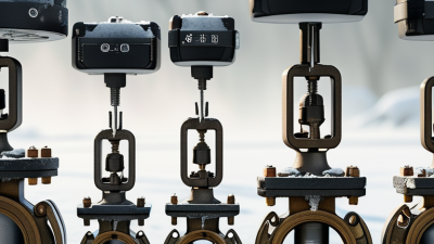
Linear valves need a different approach. Globe, gate, and diaphragm valves often use linear pneumatic actuators. Their stroke length must match the valve stem movement precisely. Too much travel can damage internal parts. Too little travel may leave the valve partly open. Measure the stroke.

Air pressure changes actuator output. Temperature, friction, and seat material also affect performance. Select an actuator with a practical torque margin, but avoid excessive oversizing. It can increase air use and create harsh closing impacts. A failed-air position deserves equal attention. Spring-return units may close or open the valve when supply air disappears. Double-acting units need a separate control decision.

In field inspections, I check mounting alignment, stem adapters, and travel stops before final installation. Small alignment errors often become large maintenance problems. I also test several operating cycles, not just one. A selection chart helps, but it cannot replace real operating data. Sometimes the first choice looks correct on paper and still needs revision.

Calculate Torque, Pressure, and Safety Margins

How to Choose a Pneumatic Valve Actuator?

Calculate Torque, Pressure, and Safety Margins

Choosing a pneumatic valve actuator starts with the valve’s real torque requirement. Record breakaway, running, and closing torque separately. A clean valve may need less torque than one exposed to sticky media or corrosion. Do not size from nominal pipe diameter alone. It can mislead you.

Use the highest required torque as your baseline. Then apply a practical safety margin, often 25–50 percent, depending on service conditions. For spring-return actuators, check the lowest available spring torque at the end of travel. That value may control the selection. Actuator output depends on air pressure, piston area, and mechanical leverage. Use the minimum plant air pressure, not the normal reading. A pressure drop during peak demand can stop the valve halfway. That is an unpleasant failure.

Calculate the available actuator torque at every operating position. Rack-and-pinion units may produce different torque at the beginning and end of rotation. Compare these values with the valve torque curve. Include pressure differential, temperature, seat friction, and possible deposits. I have seen calculations fail because engineers used clean, dry test data. Field conditions were less polite. The calculation is rarely perfect. Confirm the result with the actuator’s certified output table, then test the assembled valve under realistic pressure. A generous margin helps, but excessive oversizing can damage seats and increase air consumption. Recheck the numbers when service conditions change.

How to Choose a Pneumatic Valve Actuator? - Calculate Torque, Pressure, and Safety Margins

Selection Dimension Formula or Check Illustrative Data Engineering Guidance
Valve operating torque Use the highest torque required during breakaway, running, seating, or emergency operation. Breakaway: 120 N·m
Running: 80 N·m
Seating: 100 N·m
Design torque: 120 N·m
Use measured valve torque or the valve manufacturer's certified torque curve. Do not size the actuator from running torque alone.
Safety factor Required actuator torque = Design valve torque × Safety factor 120 N·m × 1.25 = 150 N·m A factor of 1.20–1.30 is commonly used for clean, predictable service. Consider 1.50 or higher for dirty, sticky, infrequently operated, or safety-critical service.
Torque margin Torque margin (%) = [(Available torque ÷ Required torque) − 1] × 100 Available torque at minimum pressure: 180 N·m
[(180 ÷ 150) − 1] × 100 = 20%
Select the actuator using its torque at the minimum available air pressure, not its maximum or nominal rating.
Supply pressure 1 bar = 100 kPa = 0.1 MPa
1 bar ≈ 14.504 psi
Normal pressure: 5.5 bar
Minimum pressure: 5.0 bar
Maximum pressure: 6.0 bar
Verify that the actuator and accessories are rated for the maximum pressure. Size the actuator at the lowest pressure that can occur during operation.
Pressure effect on output torque For many pneumatic actuators, output force and torque approximately increase with absolute pressure over the specified operating range. If torque is 180 N·m at 5.0 bar, an approximate value at 4.0 bar is:
180 × (4.0 ÷ 5.0) = 144 N·m
This is a preliminary estimate only. Use the actuator's actual torque curve because friction, spring force, geometry, and end-of-stroke characteristics affect output.
Piston force calculation F = P × A
A = πD² ÷ 4
Pressure: 5 bar = 500,000 Pa
Bore: 100 mm = 0.10 m
Area: 0.00785 m²
Ideal force: 500,000 × 0.00785 = 3,927 N
Use effective piston area. For a single-rod cylinder, subtract the rod area on the return stroke.
Torque from linear force T = F × r × η Force: 3,927 N
Effective lever arm: 0.05 m
Estimated efficiency: 85%
3,927 × 0.05 × 0.85 = 166.9 N·m
For rack-and-pinion or scotch-yoke designs, use the manufacturer's torque curve because the effective lever arm changes through the rotation.
Actuator type Match the actuator motion to the valve motion. Quarter-turn valves: ball, butterfly, and plug valves
Linear valves: gate, globe, and diaphragm valves
Use a rotary actuator for quarter-turn valves and a linear actuator or pneumatic cylinder for valves requiring linear travel.
Double-acting or spring-return Choose according to the required failure position and available instrument air. Double-acting: air opens and closes the valve
Spring-return: air moves the valve in one direction; springs return it when air is lost
Spring-return actuators require spring torque to be checked at both the start and end of the stroke. The weakest spring position must still exceed the required valve torque.
Operating temperature Check actuator, seals, lubricant, solenoid, and position-switch temperature limits. Process temperature: 80°C
Ambient temperature: −10°C to 45°C
High or low temperatures can change seal friction, lubricant viscosity, and available torque. Select materials and accessories for the complete temperature range.
Air quality Check filtration, moisture, oil content, and dew point requirements. Recommended preparation: filtered and regulated instrument air; typical filter rating: 5 µm or finer where required by the equipment specification Water, particulates, and incompatible lubricants can increase friction and shorten seal life. Follow the actuator maintenance instructions.
Cycle speed and air consumption Confirm required cycle time and available air-flow capacity. Air consumption is commonly stated as standard litres per cycle or standard cubic feet per cycle. Required cycle time: 8 seconds
Available instrument-air flow: 250 NL/min
Use properly sized tubing, solenoid valves, flow controls, and exhaust silencers. Excessively restricted exhaust can slow or destabilize the actuator.
Final selection example Required torque = Valve design torque × Safety factor Valve design torque: 120 N·m
Safety factor: 1.25
Required torque: 150 N·m
Selected actuator output at 5.0 bar: 180 N·m
Torque margin: 20%
The selection is acceptable for this illustrative case, provided the actuator torque curve, mounting interface, pressure rating, operating temperature, and failure position are all suitable.

Select Materials, Controls, and Air Supply Options

How to Choose a Pneumatic Valve Actuator?

Material selection should follow the valve’s environment, not only its purchase price. Aluminum housings suit many dry indoor systems. Stainless steel is safer near washdown areas, salt, or corrosive chemicals. Check shaft seals carefully. Heat, dust, and ultraviolet exposure can shorten elastomer life. ISO 12944 corrosion categories help engineers assess atmospheric risk, although site conditions can be messier than the classification suggests. A practical test includes temperature, humidity, cleaning chemicals, and installation space.

Controls determine how accurately the actuator responds. On-off valves may need a solenoid valve, position feedback, and a local manual override. Modulating service requires a positioner and stable control signals. Specify the required failure action: fail-open, fail-closed, or fail-in-place. IEC 61508 principles can support safety decisions, but certification alone does not fix poor sizing. I have seen control problems blamed on electronics when the real fault was restricted tubing.

Air supply deserves equal attention. The U.S. Department of Energy reports that compressed-air leaks can waste 20–30% of compressor output in poorly maintained systems. Install a filter, regulator, and drain near the actuator. ISO 8573-1 defines air-quality classes for particles, water, and oil. Select the class from the actuator and process requirements, not habit. Keep pressure losses visible with gauges. Oversizing seems conservative, yet it can increase air use and slow response. Small tubing may reduce cost, but it can starve the actuator during rapid cycling. Recheck the calculation under cold-start conditions.

Verify Installation, Maintenance, and Operating Compatibility

How to Choose a Pneumatic Valve Actuator?

Choosing a pneumatic valve actuator starts with the real installation, not only the valve size. Check mounting dimensions, shaft geometry, available air pressure, and the required fail position.

A compact actuator may fit the drawing but fail inside a crowded cabinet. Measure clearance around tubing connections and access panels.

Also confirm operating temperature, humidity, dust, and possible chemical exposure. These details often decide whether the actuator performs reliably.

Maintenance access matters just as much. Inspect seals, fasteners, air lines, and manual override components during routine service.

The actuator should allow safe inspection without removing nearby equipment.

Use clean, dry air at the pressure specified by the manufacturer. Excess water can damage internal parts, while excessive pressure may shorten seal life.

I once underestimated cycle frequency on a production line. The actuator worked initially, but repeated movement exposed the mistake. Calculate expected cycles, response time, torque, and safety requirements before approval. Recheck the figures during commissioning.

Tips:

Test the complete valve assembly, not the actuator alone. Watch for slow movement, air leakage, unusual noise, or incomplete closure.

Record supply pressure and cycle time under normal load. Verify electrical accessories, position indicators, and control signals together.

Leave room for future servicing. A small access gap saves considerable labor later.

When conditions are uncertain, consult qualified engineering personnel and compare verified documentation with actual site measurements. Assumptions are risky.